Chapter 1: BASIC INSTRUMENT FLYING
1.1. Instrument Categories.
Aircraft performance is achieved by controlling the aircraft attitude and power. Aircraft attitude is the relationship of its longitudinal and lateral axes to the Earth's horizon. An aircraft is flown in instrument flight by controlling the attitude and power as necessary to produce the desired performance. This is known as the "control and performance concept" of attitude instrument flying (Figure 1.1) and can be applied to any basic instrument maneuver. The three general categories of instruments are:
1.1.1. Control instruments: Display immediate attitude and power indications and are calibrated to permit adjustments in definite amounts. Control is monitored by referencing the attitude direction indicators (ADIs). Measures of power vary with aircraft and include tachometers, engine pressure ratio (EPR), manifold pressure, fuel flow, torque, etc.
1.1.2. Performance instruments: Indicate the results of pilot control input. Performance instruments include the altimeter, airspeed or mach indicator, vertical velocity indicator, heading indicator, angle of attack indicator, and turn and slip indicator.
1.1.3. Navigation Instruments indicate the position of the aircraft in relation to a selected navigation facility or fix. This group of instruments includes various types of course indicators, range indicators, glide slope indicators, and bearing pointers.
Figure 1.1. Attitude Instrument Flying.
1.2. Control and Performance Concept.
The pilot establishes an attitude and power setting that will result in the desired aircraft performance, trims the aircraft for hands-off flight, and references the performance instruments. If deviations occur, power and attitude corrections are made and the process repeats. In general, small smooth corrections coupled with an efficient crosscheck will result in the best aircraft performance. (The instrument crosscheck is discussed later in the chapter.).
1.2.1. Attitude Control. Proper instrument aircraft attitude control is accomplished by making appropriate control inputs and verifying the result on the ADI. The ADI provides an immediate, direct and corresponding indication of any change in aircraft pitch or bank.
1.2.1.1. Pitch Control. Changing the vertical position of the miniature aircraft or fuselage dot in relation to the artificial horizon makes pitch changes. These changes are measured in degrees or bar widths depending on the type of ADI.
1.2.1.2. Bank Control. Changing the "bank attitude" or bank pointers a definite amount in relation to the bank scale makes bank changes. The bank scale is normally graduated at 0°, 10°, 20°, 30°, 60°, and 90° and may be located at the top or bottom of the attitude reference.
1.2.1.3. Yaw axis control. Yaw control references on an ADI are normally located at the bottom of the case in the form of a ball in a fluid filled tube and a turn needle or on an indicator below the ADI on the MFD if equipped with electronic flight instrument display. These indicators are called the turn and slip indicator but are commonly referred to as the "needle and ball." The use of rudders or anti-torque to maintain coordinated flight is important in all aircraft but is critical to instrument flight in helicopters. Yaw is usually the most unstable axis in helicopters, particularly in those not equipped with a Stability Augmentation System (SAS). The instability in the yaw axis is compounded by power changes that cause a yawing moment which can cause induced vertigo. Pilot anticipation and smoothness of rudder or anti-torque inputs during power changes will keep yaw moments to a minimum.
1.2.2. Power Control. Proper power control allows the pilot to smoothly establish or maintain desired airspeeds in coordination with attitude changes. Power changes are made by throttle adjustments or collective pitch in helicopters and referencing power indicators. With experience pilots learn approximately how far to move the throttles or collective to change the power a given amount. Learning how to set approximate power settings, crosschecking and then fine tuning prevents fixating on performance instruments and overcontrolling power.
1.2.3. Trim. Aircraft trim relieves control pressure and improves attitude control. The decrease in attention required to maintain aircraft attitude increases the amount of attention the pilot can give to clearing and other cockpit duties.
1.2.3.1. To trim properly, first use the controls to set the desired aircraft attitude, then use the trim to relieve the control pressure. Do not use trim to control the aircraft.
1.2.3.2. Any change in attitude, power or airspeed will usually result in the need for a trim adjustment. Experienced pilots develop a feel for minor out-of-trim conditions and correct them smoothly. In asymmetric power situations (e.g. engine failure) trim can be useful for reducing cockpit workload and enhancing pilot efficiency.
Figure 1.2. Instrument Cross-Check Technique.
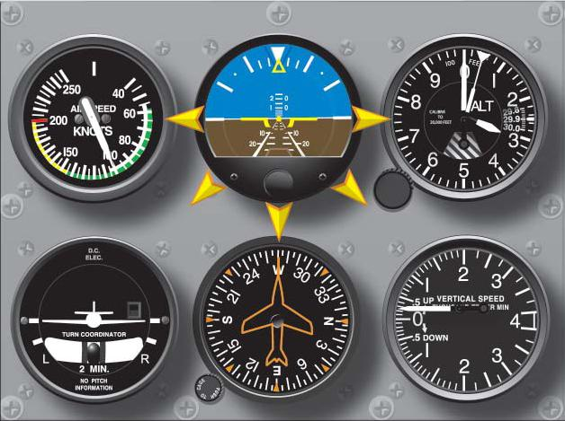
1.2.4. Cross-Check Technique (Figure 1.2).
1.2.4.1. Crosschecking is the efficient division of attention between control and performance instruments, the ability to interpret the information given by those instruments, and the correction of any discrepancies noted in aircraft flight parameters. The act of crosschecking is often compared to the hub and spokes of a wagon wheel where the ADI is the hub and the other instruments are the spokes. In general, the crosscheck will progress from the ADI, out to another instrument, back to the ADI and then out again.
1.2.4.2. Performance Instrument Lag. Due to mechanical characteristics of some instruments and the inertial properties of flight, there is an inherent lag between a control input and the appearance of the effects of that input on the performance instruments. A common mistake is to watch the performance instruments while making control inputs, resulting in overshoot of desired flight parameters. Experienced pilots learn to make small calculated inputs and allow the performance instruments to catch up before making another input.
1.2.4.3. Fixating on a single instrument is a common and dangerous error made by inexperienced pilots. If one flight parameter, (e.g. altitude) is frequently wandering, the pilot will devote too much time to the altimeter and lose track of other critical parameters (e.g. attitude). The pilot must remember that the attitude of the aircraft, not the altimeter, is what is causing the aircraft to be off altitude. Returning to the basic crosscheck flow will solve the problem and prevent the aircraft from entering a dangerous attitude.
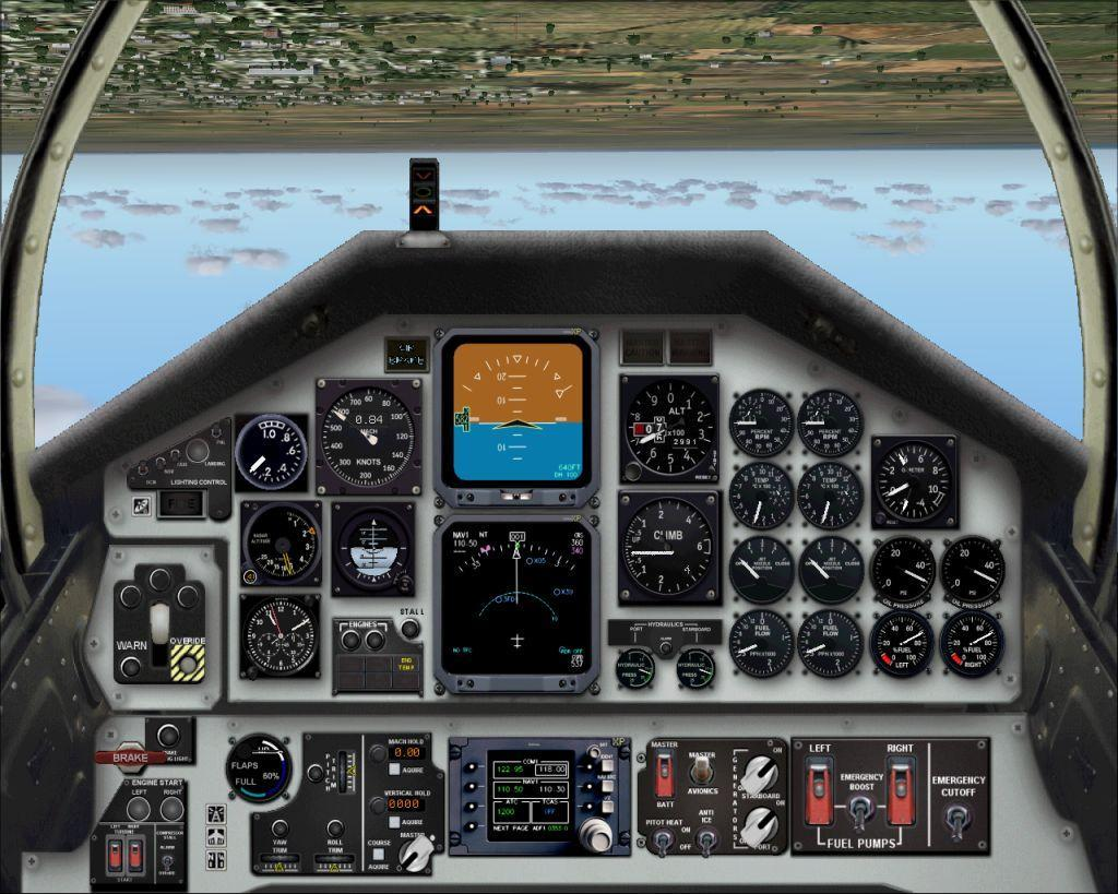
Figure 1.3. Typical Instrument Cockpit Layout.
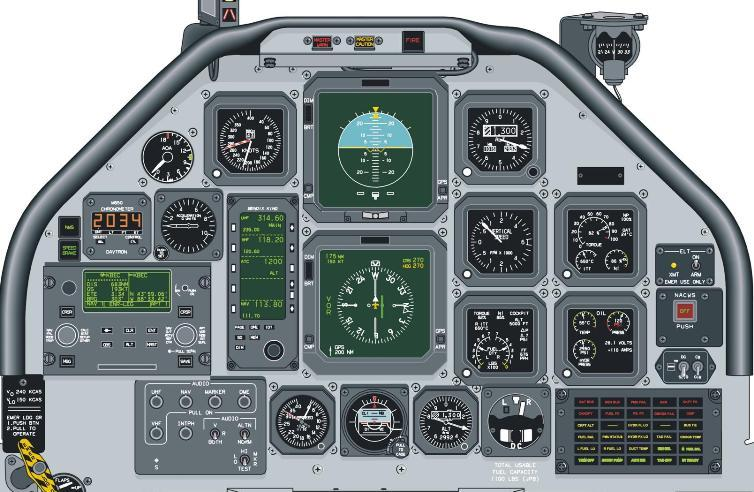
1.3. Display of Flight Instrumentation (Figure 1.3).
Display options vary widely from aircraft to aircraft and incorporate different symbologies and terminology for similar functions. Electronic displays allow the pilot to optimize cockpit instrumentation for a particular mission by decluttering, removing, or relocating presentations. However, with very few exceptions, Air Force instrument cockpits must adhere to the following specific rules of instrumentation, equipage and setup:
1.3.1. Primary Flight Instrumentation. Primary flight instrumentation must always be present. It must provide full-time attitude, altitude, and airspeed information, an immediately discernible attitude recognition capability, an unusual attitude recovery capability, and complete fault indications.
1.3.2. Position of Flight Instrumentation. Primary Flight Instrumentation information must be positioned and arranged in a manner that enables the pilot to perform an efficient crosscheck.
1.3.3. Standardization of Flight Instrumentation. Primary Flight Instrumentation must be standardized in terminology, symbology, mechanization, and arrangement. Standardization of instrumentation display elements provides a common training base and allows the retention of good flying habits during transition to different aircraft.