Chapter 5: NAVIGATION TECHNIQUES AND PROCEDURES
5.1. Application.
Instrument procedures are flown using a combination of techniques (arc to radial, radial to arc, course intercepts, etc.). Individual aircraft flight manuals should provide proper procedures for using the navigation equipment installed.
5.1.1. Where procedures depict a ground track, the pilot is expected to correct for known wind conditions. In general, the only time wind correction should not be applied is during radar vectors. The following general procedures apply to all aircraft.
5.1.1.1. Unless otherwise authorized by ATC (or as necessary for safety if ATC coordination is not possible), no person may operate an aircraft within controlled airspace under IFR except as follows:
5.1.1.1.1. On a Federal airway, along the centerline of that airway.
5.1.1.1.2. Along the direct course between navigational aids or fixes defining a route.
5.1.2. Utilizing ground based NAVAIDS.
5.1.2.1. Tune and Identify. The pilot will tune or select the desired frequency or channel, then positively identify the selected station via an aural (Morse Code) or visual (alphanumeric) signal.
5.1.2.1.1. For aircraft with the capability to translate Morse code station identification into an alphanumeric visual display, it is acceptable to use the visual display as the sole means of identifying the station identification provided: (MAJCOMs will determine which aircraft can use this method for identifying NAVAIDS.)
5.1.2.1.1.1. The alphanumeric visual display must always be in view of the pilot.
5.1.2.1.1.2. Loss of the Morse code station identification will cause the alphanumeric visual display to immediately disappear, or a warning to be displayed.
5.1.2.1.1.2.1. WARNING: It is imperative that crews are cognizant of what station identification is being displayed. For example, if the station identification being displayed is from the DME portion of a VOR/DME station, then only the DME alphanumeric display may be used. The VOR azimuth station must still be identified aurally.
5.1.2.1.1.2.2. WARNING: Voice communication is possible on VOR, ILS, and ADF frequencies. The only positive method of identifying a station is by its Morse code identifier (either aurally or alphanumeric display) or (for VORs) the recorded automatic voice identification, indicated by the word "VOR" following the station name. Identifying a NAVAID by listening to other voice transmissions broadcast on a Flight Service Station or other facility is not a reliable method of station identification and shall not be used.
5.1.2.1.2. VOR. The station identification may be a repeated three-letter Morse code group, or a three-letter Morse code group alternating with a recorded voice identifier.
5.1.2.1.3. TACAN. The TACAN station transmits an aural three-letter Morse code identifier approximately every 35 seconds.
5.1.2.1.4. NDB/ADF. The nondirectional radio beacon transmits a repeated two or three-letter Morse code group depending on power output.
5.1.2.1.5. ILS. The ILS localizer transmitter puts out a repeated four-letter Morse code group. In the US, the first letter of the identifier is always "I" to denote the facility as an ILS.
5.1.3. Monitor. The pilot will monitor station identification (either aural or visual as applicable) to ensure a reliable signal is being transmitted. Removal of identification serves as a warning to pilots that the facility is officially off the air for tune-up or repairs and may be unreliable even though intermittent or constant signals are received. The navigation signal must be considered unreliable when the station identifier is not being received. For NDBs, there is a direct correlation between the strength of the identifier and the strength and reliability of the signal with no off flags to indicate loss of signal. Therefore, on approaches that require an NDB, pilots will monitor the NDB identifier for the entire approach.
5.1.4. Select. The pilot will select proper position for the navigation system switches.
5.1.5. Set. The pilot will set the selector switches to display the desired information on the navigation instruments.
5.1.6. Check. The pilot will check the appropriate instrument indicators for proper operation.
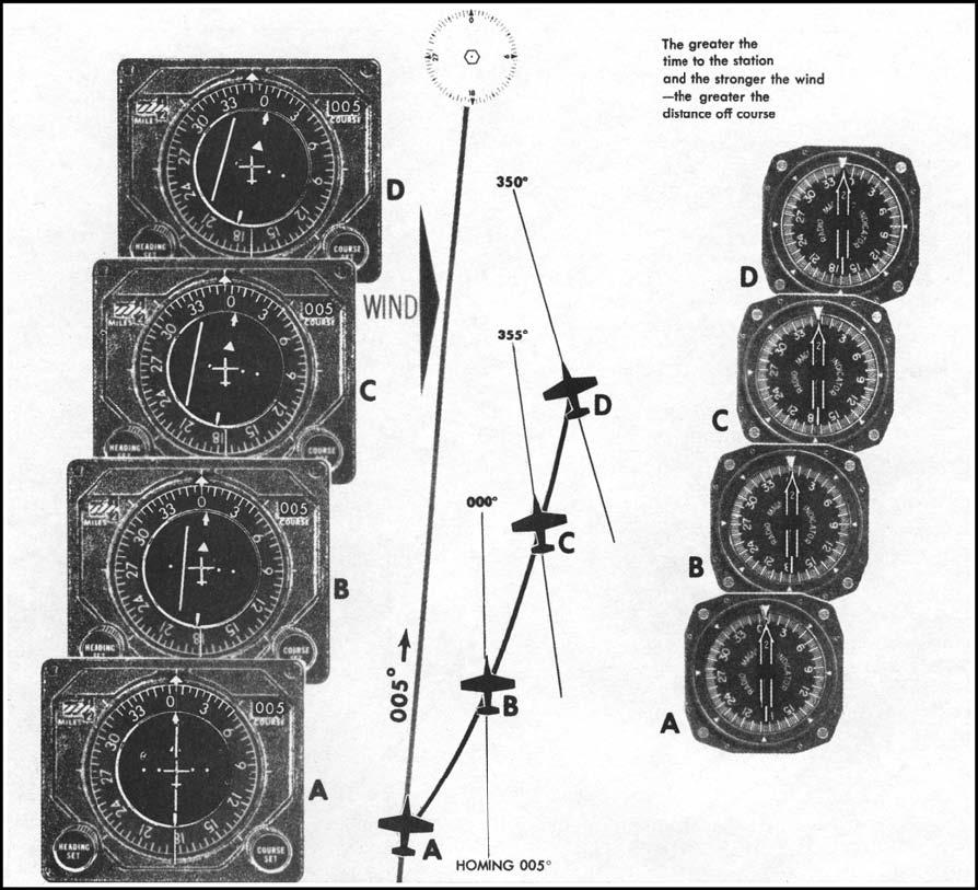
5.2. Homing to a Station (Figure 5.1).
Homing occurs when the pilot places the head of the bearing pointer under the upper lubber line (or Top Index) and makes periodic heading changes to keep it there. Failure to apply wind drift corrections results in a curved flight path to the station.
Figure 5.1. Curved Flight Path as a Result of Homing with a Crosswind.
5.3. Proceeding Direct to a Station.
Turn the aircraft in the shorter direction to place the head of the bearing pointer under the top index or upper lubber line. Center the CDI with a TO indication (N/A RMI only) and apply wind drift corrections to maintain the selected course to the station.
5.3.1. If either the compass card or the bearing pointer is inoperative, a course indicator or HSI may be used to determine the bearing to the station by rotating the course set knob until the CDI centers and "TO" is read in the "TO-FROM" indicator. The magnetic bearing from the aircraft to the station then appears in the course selector window. Pilots will attempt to verify bearing information by any other means available before considering it reliable.
5.4. Course Intercepts.
5.4.1. Successful Course Interception. Course interceptions are performed in many phases of instrument navigation. To ensure successful course interception, an intercept heading must be used that results in an angle or rate of intercept sufficient to complete a particular intercept problem.
5.4.1.1. Intercept Heading. The intercept heading (aircraft heading) is the heading determined to solve an intercept problem. When selecting an intercept heading, the essential factor is the relationship between distance from the station and the number of degrees the aircraft is displaced from the course. Adjustments to the intercept heading may be necessary to achieve a more desirable rate of intercept.
5.4.1.1.1. A technique for determining intercept headings is:
5.4.1.1.1.1. Inbound: From the desired course, look in the shorter direction to the head of the bearing pointer. Continue beyond the head of the bearing pointer by 30 degrees or the number of degrees off course, whichever is less. This will give a recommended intercept angle of 30 degrees or less. Any heading beyond the bearing pointer, within 90° of the desired inbound course, is a no-wind intercept heading.
5.4.1.1.1.2. Outbound: From the tail of the bearing pointer, move in the shorter direction to the desired course. Continue beyond the course by 45 degrees, or the number of degrees off course, whichever is less. This will give the recommended intercept angle of 45 degrees or less. Any heading beyond the desired course, within 90°, is a no-wind intercept heading.
5.4.1.2. Angle of Intercept. The angle of intercept is the angular difference between the heading of the aircraft (intercept heading) and the desired course. The minimum acceptable angle of intercept for an inbound course interception must be greater than the number of degrees the aircraft is displaced from the desired course. The angle of intercept should not exceed 90°.
5.4.1.3. Rate of Intercept. The rate of intercept is determined by observing bearing pointer and CDI movement. The rate of intercept is a result of intercept angle, groundspeed, distance from the station, and if you are proceeding to or from the station.
5.4.1.4. Completing the Intercept.
5.4.1.4.1. Lead point. A lead point to roll out on the course must be determined because of turn radius of the aircraft. The lead point is determined by comparing bearing pointer or CDI movement with the time required to turn to course. Refer to AFMAN 11-217V3 for techniques to determine a lead point.
5.4.1.4.2. Rate of intercept. To determine the rate of intercept, monitor the bearing pointer or CDI movement.
5.4.1.4.3. Turn. The time required to make the turn to course is determined by the intercept angle and the aircraft turn rate.
5.4.1.4.4. Complete the intercept. Use the CDI, when available, for completing the course intercept.
5.4.1.4.5. Undershoot or Overshoot. If it is obvious that the selected lead point will result in undershooting the desired course, either reduce the angle of bank or roll out of the turn and resume the intercept. If the selected lead point results in an overshoot, continue the turn and roll out with a correction back to the course.
5.4.1.4.6. Maintain course. The aircraft is considered to be maintaining the course centerline when the CDI is centered or the bearing pointer points to the desired course. A correction for known winds should be applied when completing the turn to a course.
5.4.1.4.7. NOTE: Pilots should always attempt to fly as close to the course centerline as possible. TERPS design criteria will provide maximum obstacle clearance protection when the course centerline is maintained.
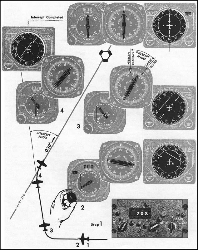
5.4.2. In-bound (HSI, CI and RMI) (Figure 5.2).
5.4.2.1. Tune and identify the station.
5.4.2.2. Set inbound course. Set the desired inbound course in the course selector window and check for a TO indication.
5.4.2.3. Turn. Turn to an intercept heading.
5.4.2.3.1. CI and RMI. Turn in the shorter direction to place the heading pointer toward the CDI. Continue the turn to place the heading pointer in the top half of the instrument case. This precludes an intercept angle in excess of 90°. Roll out with the RMI/BDHI bearing pointer between the desired inbound course and top index. The angle of intercept must be greater than the number of degrees off course, not to exceed 90°. The intercept heading may be adjusted within these limits to achieve the most desirable rate of intercept. Displacing the bearing pointer approximately 30° from the top index will normally ensure a moderate rate of intercept.
5.4.2.3.2. HSI. Turn in the shorter direction toward the CDI. The shorter direction is displayed by the aircraft symbol and CDI relationship. Continue the turn to place the head of the course arrow in the top half of the instrument case. This precludes an intercept angle in excess of 90°. Roll out of the turn when the bearing pointer is between the upper lubber line and the head of the course arrow to establish an intercept heading. Displacing the bearing pointer 30° from the upper lubber line will normally ensure a moderate rate of intercept. The aircraft symbol will appear to be proceeding toward the CDI at an intercept angle equal to the angle formed between the upper lubber line and the head of the course arrow. The angle of intercept must be greater than the number of degrees off course, but not more than 90°.
5.4.2.4. Maintain intercept. Maintain the intercept heading until a lead point is reached, then complete the intercept. The lead point depends on bearing pointer or CDI rate of movement and the time required to turn on course.
Figure 5.2. Inbound Course Interceptions (HSI, CI and RMI).
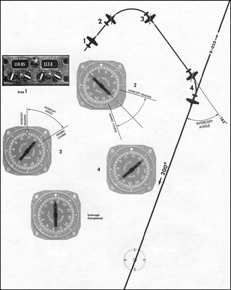
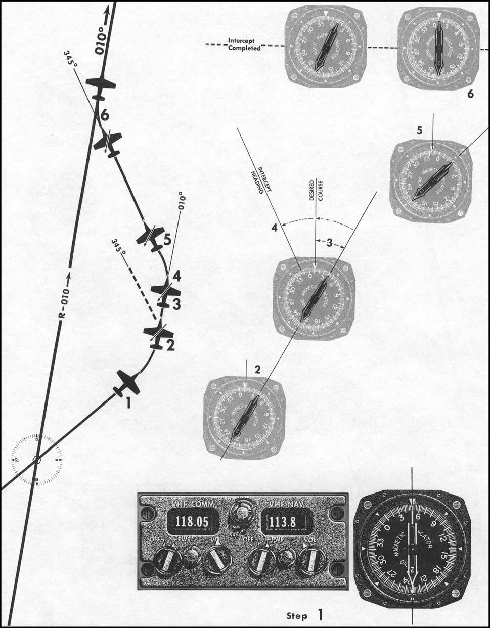
5.4.3. Inbound (RMI Only) (Figure 5.3).
5.4.3.1. Tune and identify. Tune and identify the station.
5.4.3.2. Determine heading. Determine an intercept heading. Locate the desired inbound course on the compass card. From the desired course, look in the shorter direction to the head of the bearing pointer. Any heading beyond the bearing pointer, within 90° of the desired inbound course, is a no-wind intercept heading. In many instances, an intercept heading selected 30° beyond the bearing pointer ensures a rate of intercept sufficient to solve the problem. An intercept angle is formed when the head of the bearing pointer is between the desired course and the top index on the RMI.
5.4.3.3. Turn. Turn in the shorter direction to the intercept heading.
5.4.3.4. Maintain intercept. Maintain the intercept heading until a lead point is reached, then complete the intercept. Lead point depends on bearing pointer rate of movement and the time required to turn on course.
Figure 5.3. Inbound Course Interceptions (RMI Only).
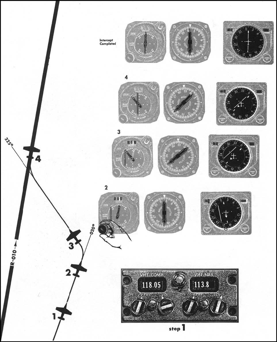
5.4.4. Outbound - Immediately After Station Passage (HSI, CI and RMI) (Figure 5.4).
5.4.4.1. Tune and Identify. Tune and identify the station. This should have already been accomplished.
5.4.4.2. Turn. Turn in the shorter direction to a heading that will parallel or intercept the outbound course. Turning to parallel the desired outbound course is always acceptable. Continuing the turn to an intercept heading may be preferable when the bearing pointer is stabilized or when you know your position in relation to the desired course. The effect that airspeed, wind, and magnitude of turn will have on aircraft position during the turn to an intercept heading should be considered.
5.4.4.3. Set course. Set the desired course in the course selector window and check for FROM indication.
5.4.4.4. Turn to Intercept. Turn to an intercept heading if not previously accomplished. Determine the number of degrees off course as indicated by CDI displacement or angular difference between the tail of the bearing pointer and the desired course. If the initial turn was to parallel the desired course, turn toward the CDI to establish an intercept angle approximately equal to the number of degrees off course. Normally, to avoid overshooting, an intercept angle greater than 45° should not be used.
5.4.4.5. Maintain. Maintain the intercept heading until a lead point is reached, then complete the intercept. The lead point depends on bearing pointer or CDI rate of movement and the time required to turn on course.
Figure 5.4. Outbound Course Interceptions-Immediately After Station Passage (HSI, CI and RMI).
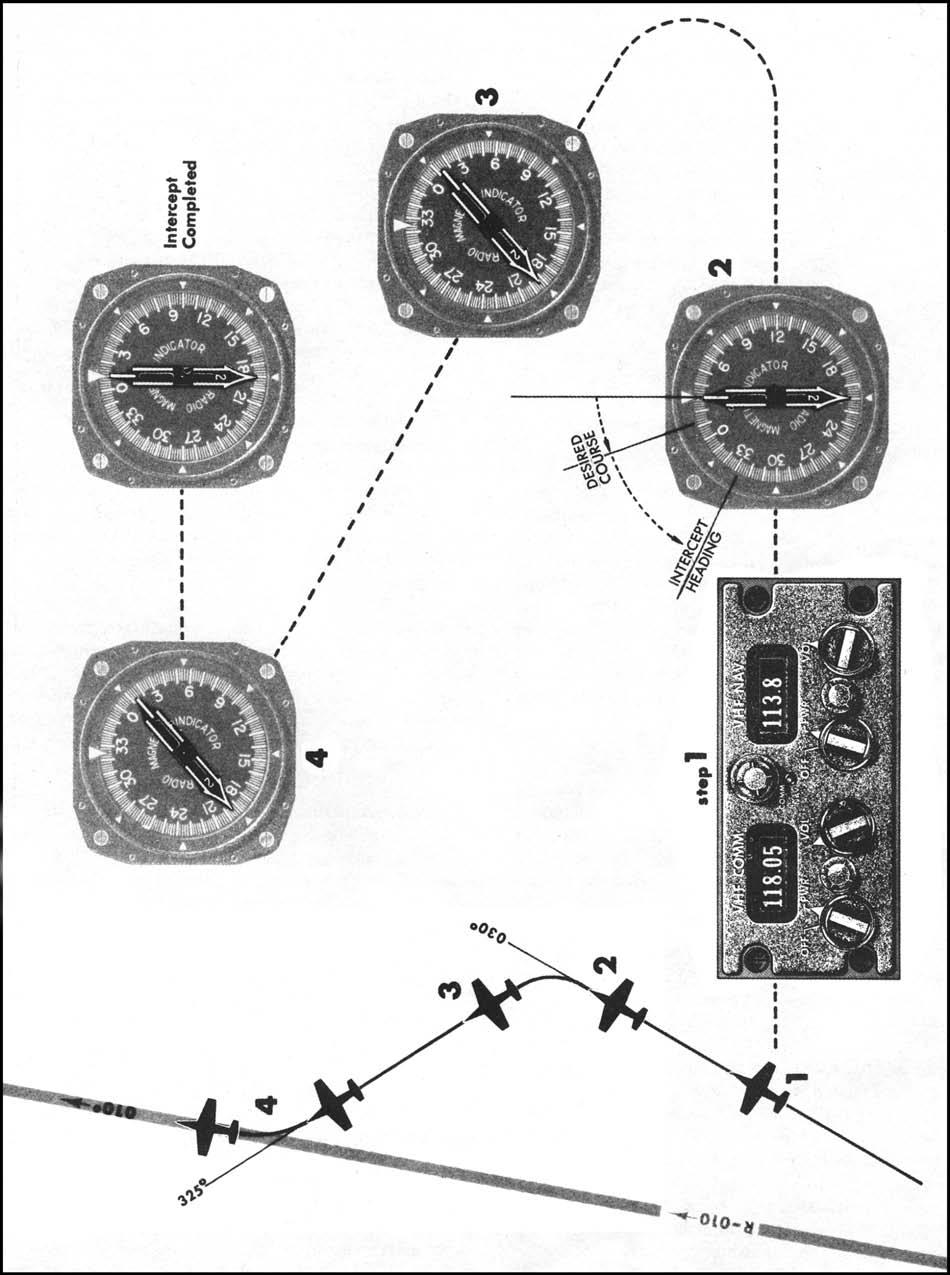
5.4.5. Outbound - Immediately After Station Passage (RMI Only) (Figure 5.5).
5.4.5.1. Tune and Identify. Tune and identify the station. This should have already been accomplished.
5.4.5.2. Turn. Turn in the shorter direction to a heading that will parallel or intercept the outbound course. Refer to paragraph 5.4.4 above (Outbound - Immediately After Station Passage (HSI and CI)).
- 5.4.5.2.1. Degrees Off Course. Determine the number of degrees off course. Note the angular difference between the tail of the bearing pointer and the desired course.
5.4.5.3. Intercept Heading. Determine an intercept heading. Determine and turn to an intercept heading if a suitable intercept angle was not established during the initial turn. Look from the tail of the bearing pointer to the desired course. Any heading beyond the desired course is a no-wind intercept heading. Turn in this direction an amount approximately equal to the number of degrees off course. Normally, to avoid overshooting the course, do not use an intercept angle greater than 45°.
- 5.4.5.3.1. Note: On some aircraft, the RMI/BDHI bearing pointer does not have a tail. In this case, turn to the magnetic heading of the desired course. Continue on the outbound magnetic heading of the desired course until the bearing pointer stabilizes. Note the number of degrees the bearing pointer is off the tail of the aircraft. This is the number of degrees off course. Any heading change in the direction toward the head of the bearing pointer is a no-wind intercept heading. Turn in the direction of the head of the bearing pointer an amount approximately equal to the number of degrees off course. Normally, to avoid overshooting the course, do not use an intercept angle greater than 45°.
5.4.5.4. Maintain. Maintain the intercept heading until a lead point is reached, then complete the intercept. The lead point depends on the bearing pointer rate of movement and the time required to turn on course.
Figure 5.5. Outbound Course Interceptions-Immediately After Station Passage (RMI Only).
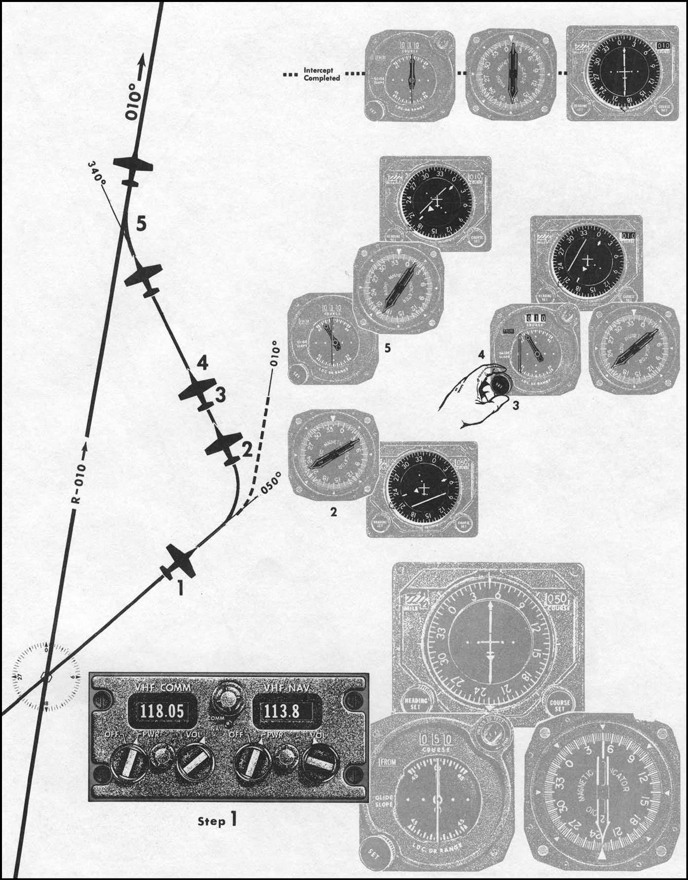
5.4.6. Outbound-Away from the Station (HSI, CI and RMI) (Figure 5.6).
5.4.6.1. Tune and identify. Tune and identify the station.
5.4.6.2. Set. Set the desired outbound course in the course selector window.
5.4.6.3. Turn. Turn to an intercept heading:
5.4.6.3.1. CI. Turn in the shorter direction to place the heading pointer toward the CDI. Continue the turn to place the heading pointer in the top half of the instrument case and roll out on an intercept heading. This precludes an intercept angle in excess of 90°. Roll out of the turn on an intercept heading with a suitable intercept angle, normally 45°. A 45° intercept angle is established by rolling out with the desired course under the appropriate 45° index, or with the heading pointer displaced 45° from the top index and toward the CDI.
5.4.6.3.2. HSI. Turn in the shorter direction toward the CDI. Continue the turn until the head of the course arrow is in the top half of the instrument case. This precludes an intercept angle in excess of 90°. Roll out of the turn on an intercept heading with a suitable angle of intercept, normally 45°. A 45° intercept angle is established by rolling out with the head of the course arrow under the appropriate 45 ° index (aircraft symbol directed toward the CDI).
5.4.6.4. Maintain. Maintain the intercept heading until a lead point is reached, then complete the intercept. The lead point depends on the bearing pointer or CDI rate of movement and the time required to turn on course.
Figure 5.6. Outbound Course Interceptions-Away From the Station (HSI, CI and RMI).
5.4.7. Outbound-Away From the Station (RMI Only) (Figure 5.7).
5.4.7.1. Tune and identify. Tune and identify the station.
5.4.7.2. Determine an intercept heading. Look from the tail of the bearing pointer past the desired course and select an intercept heading. Any heading beyond the desired course, within 90°, is a no-wind intercept heading. A heading selected 45° beyond the desired course will normally ensure a moderate rate of intercept.
- 5.4.7.2.1. Note: On some aircraft, the RMI or BDHI bearing pointer does not have a tail. In this case, turn the shorter direction to the outbound magnetic heading of the desired course. Note the number of degrees the bearing pointer is off the tail of the aircraft. This is the number of degrees off course. Any heading change in the direction toward the head of the bearing pointer within 90° is a no-wind intercept heading. A turn in the direction of the head of the bearing pointer of 45° past the desired course will normally ensure a moderate rate of intercept.
5.4.7.3. Turn. Turn in the shorter direction to the intercept heading.
5.4.7.4. Maintain. Maintain the intercept heading until a lead point is reached, then complete the intercept. The lead point depends on the bearing pointer or CDI rate of movement and the time required to turn on course.
Figure 5.7. Outbound Course Interceptions-Away From the Station (RMI Only).
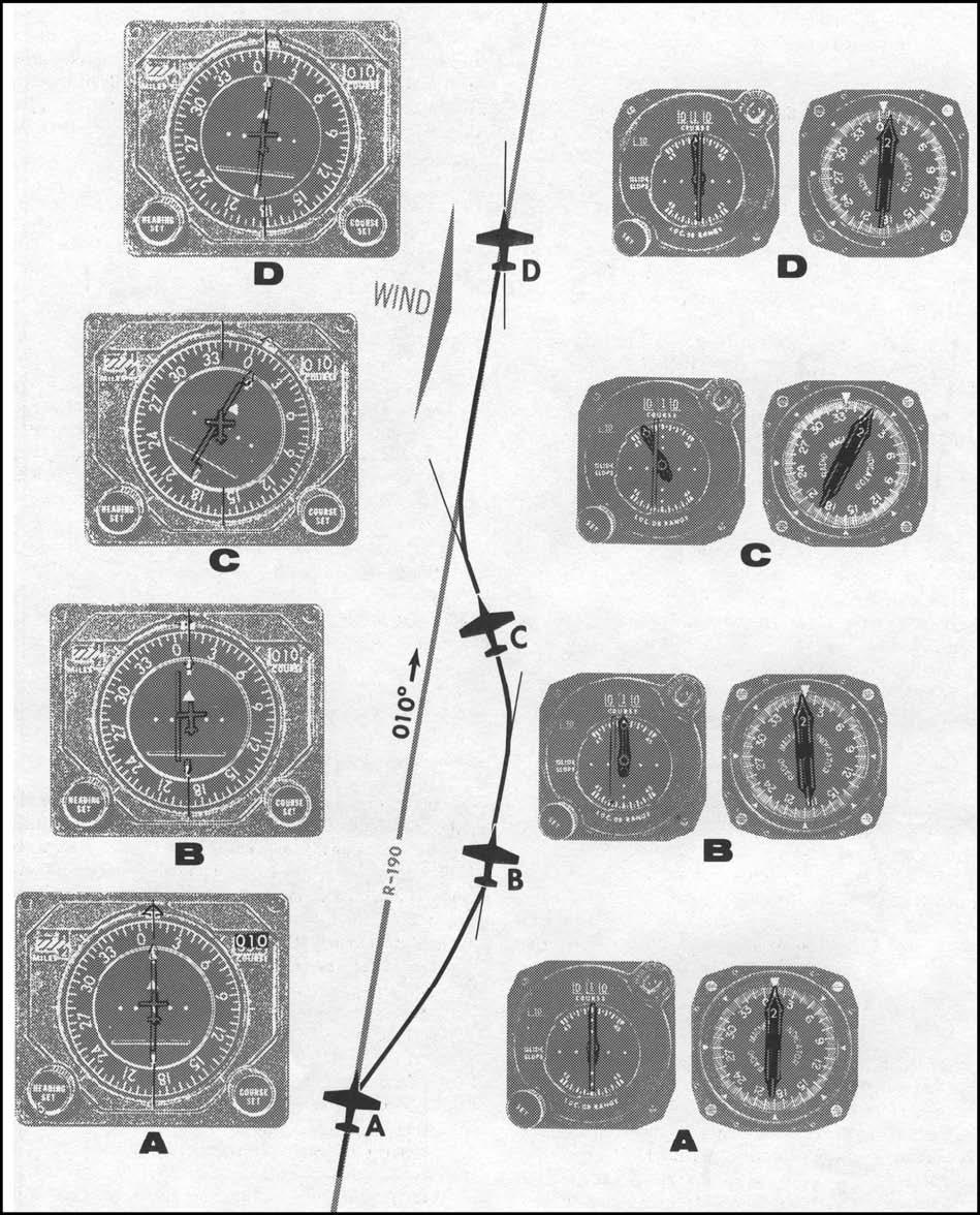
5.4.8. Maintaining Course (Figure 5.8). To maintain course, fly a heading estimated to keep the aircraft on the selected course. If the CDI or bearing pointer indicates a deviation from the desired course, return to course avoiding excessive intercept angles. After returning to course, again estimate the drift correction required to keep the CDI centered or the bearing pointer pointing to the desired course. (The CDI and bearing pointer may show a rapid movement from the on-course indication when close to the station. In this situation, avoid making large heading changes because actual course deviation is probably small due to proximity to the station).
Figure 5.8. Maintaining Course.
5.5. Station Passage.
5.5.1. VOR and VOR/DME. Station passage occurs when the TO-FROM indicator makes the first positive change to FROM. For RMI/BDHI only, station passage is determined when the bearing pointer passes 90 degrees to the inbound course.
5.5.2. TACAN. Station passage occurs when the range indicator stops decreasing.
5.5.3. ADF. Station passage occurs when the bearing pointer passes 90° to the inbound course.
- 5.5.3.1. NOTE: When established in an NDB holding pattern, subsequent station passage occurs at the first definite move by the bearing pointer through the 45° index on the RMI.
5.6. Groundspeed Check.
Groundspeed checks are done to aid in calculating ETAs to fixes, which are useful for position reports, fuel computations and other mission timing problems.
5.6.1. Conditions. A groundspeed check can be made while maintaining a course to or from a TACAN/VORTAC station. As a guide, however, groundspeed checks should be performed only when the aircraft slant range distance is more than the aircraft altitude divided by 1,000. For example, if the aircraft is at FL 200, groundspeed checks should be performed when beyond 20 nautical miles. Checks made below 5,000 feet are accurate at any distance.
5.6.2. Begin Timing. To perform the groundspeed check, begin timing when the range indicator shows a whole number. After the predetermined time has elapsed, check the range indicator and note the distance flown. Apply the following formula to determine groundspeed: Multiply the distance flown times 60 and then divide the product by the elapsed time in minutes. For example, if you fly 12 NM in 2 minutes, then your groundspeed is 360 knots. ((12 NM x 60)/2 min = 360 knots)
- 5.6.2.1. NOTE: For precise computation, time for longer periods and solve the problems on a computer. To simplify computations, use a 2-minute time check and multiply the distance traveled by 30, a 3-minute time check, distance times 20; or a 6-minute time check, distance times 10. A rapid groundspeed check can be accomplished by timing the range indicator for 36 seconds and multiplying the distance traveled by 100.
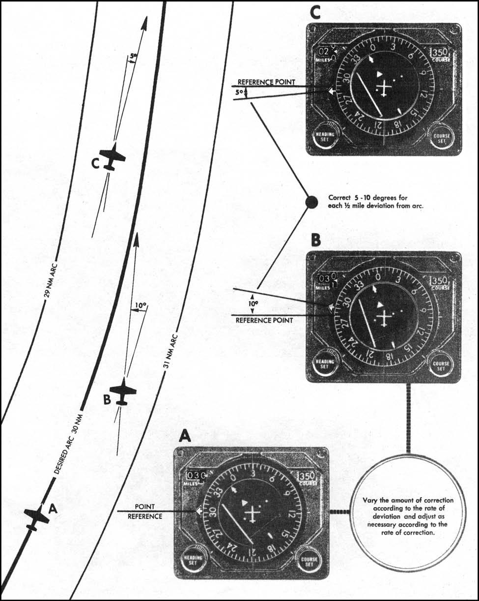
Figure 5.9. Arc Interception From a Radial.

5.7. Arc/Radial Intercepts.
TACAN and VOR/DME arcs are used during many phases of flight. Arcs are normally intercepted from radials (either inbound or outbound) and vice-versa, making the turn from one to the other, in general, 90° of heading change . Use accurate lead points and account for variations in aircraft turn radius due to winds to prevent excessive under or overshoots.
5.7.1. Arc Interception from a Radial (Figure 5.9). Tune and identify the NAVAID used for the intercept and determine the direction of turn. Using aircraft calculations found in AFMAN 11-217V3, determine the lead point necessary to intercept the arc. When the lead point is reached, turn to place the bearing pointer on the 90° index.
5.7.1.1. Corrections. If the aircraft is outside of the desired arc, turn to place the bearing pointer slightly above the 90° index. If inside, turn to place the bearing pointer slightly below the 90° index. (Rule of Thumb: Displace the bearing pointer 5° below the reference point for each one-half mile deviation to the inside of the arc, and 10° above the reference point for each half mile outside the arc.)
5.7.1.2. While on the arc, as the bearing pointer falls, continue to make small turns to keep it on the 90° index. Alternatively, a series of short straight legs may be flown allowing the bearing pointer to fall a few degrees below the 90° index then turning to place the bearing pointer a few degrees above the 90° index. When using this technique, the aircraft will fly slightly outside and inside the arc alternatively on each leg (Figure
5.10).
Figure 5.10. Correcting to Maintain an Arc.
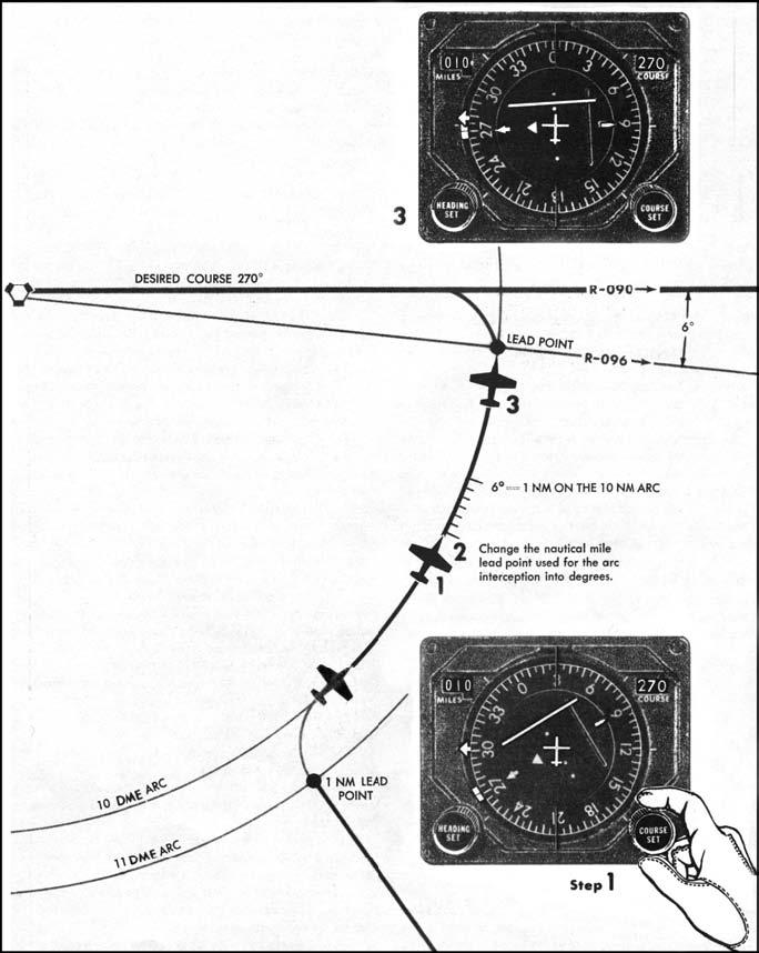
5.7.2. Radial Interception From an Arc (Figure 5.11). Tune and identify the NAVAID used for the intercept and determine the direction of turn. Using aircraft calculations found in AFMAN 11-217V3, determine the lead point necessary to intercept the arc. When the lead point is reached, roll to the bank angle used in the lead point calculation and turn to roll out on the radial.
Figure 5.11. Radial Interception From an Arc.
5.8. Proceeding Direct to a VOR/DME or TACAN Fix.
Proceeding directly to a radial/DME fix without RNAV equipment is not a normal form of navigation in the NAS. It can, however, be a useful technique for backing up RNAV equipment or navigating in a loss of communication situation. Bearing and range information from a VOR/DME or TACAN facility is sufficient for navigating direct to any fix within reception range.
5.8.1. In order to legally conform to NAS area navigation procedures and the national route program (NRP) as outlined in FLIP GP chapter 4 and FAA AC 90-91, USAF pilots and air traffic controllers should not file, give, or accept a clearance (as applicable) that requires an aircraft to navigate direct to a radial/DME fix (perform a fix-to-fix) except under the following circumstances:
5.8.1.1. The primary navigation equipment onboard the aircraft is either area navigation (RNAV) or advanced RNAV capable and operating normally.
5.8.1.2. Flight will be conducted where radar monitoring by air traffic control (ATC) is available.
5.8.1.3. Locally defined arrival/departure procedures require the navigation to/from a radial-DME fix for the sequencing of aircraft. Locally defined procedures must be evaluated by TERPS and flight checked if flown in instrument meteorological conditions (IMC) and radar monitoring is not available.
5.8.1.4. Operational necessity dictates (i.e. filing and flying an air refueling track) or conforms to military enroute operations.
5.8.2. When operating in the NAS and given a clearance to proceed to a radial/DME fix, unless the aircraft capability or operations meet one of the parameters defined above, pilots should reply with "unable" and state the appropriate suffix code defined in FLIP GP chapter 4. Under these circumstances, ATC should provide navigation guidance to the radial/DME fix either via radar vectors or an alternate routing.
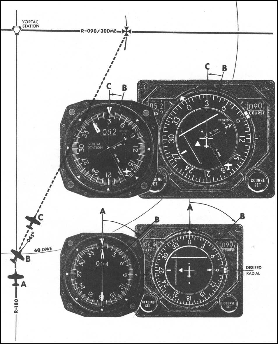
5.8.3. The following are some techniques to accomplish a fix-to-fix (Figure 5.12.):
5.8.3.1. Tune the TACAN or VOR/DME equipment (VOR and DME stations must be collocated). Then visualize the navigational situation on the HSI or RMI compass card. The NAVAID will be represented by the center of the compass card. The outer ring of the compass card will represent the greater of either the aircraft's current DME or the DME of the fix.
5.8.3.2. Turn in the shortest direction to a heading somewhere between the head of the bearing pointer and the radial of the desired fix. (Position B of Figure 5.12) If the DME of the fix is greater than the aircraft's current DME, the heading will be closer to the desired radial and vice-versa. This initial heading will get the aircraft moving in the general direction of the fix until the following procedures can fine-tune the heading.
5.8.3.3. To fine-tune the heading to the desired fix, mentally place the aircraft and the desired fix on their respective radials at the appropriate relative position from the center of the compass card (NAVAID). Turn the aircraft until the line between these two points is parallel to a line from the center of the compass card and the upper lubber line with the two fix points vertically one above the other. (Position C of Figure 5.12)
5.8.3.4. Update the fix-to-fix periodically remembering that the relative size of the compass card will change as the airplane moves in relation to the NAVAID. If the initial heading does not keep the aircraft moving toward the fix, there is probably a wind effect. When making adjustments to the fix-to-fix heading, take this wind effect into account in the new heading.
Figure 5.12. Proceeding Direct to a DME Fix.
5.9. Area Navigation.
(RNAV) A method of navigation using a variety of onboard equipment including Inertial Navigation System (INS), TACAN/VOR/DME-based Flight Management Systems (FMS), Integrated/Embedded GPS, DME/DME/IRU (if certified for IFR navigation) or LORAN-C that allows the pilot to fly directly to predetermined geographical positions (waypoints) or define routes or instrument procedures in terms of latitude and longitude or radial/distance relative to a ground based navigation facility.
5.9.1. In order to be considered RNAV capable, an aircraft must be able to display a course from a given point (waypoint) to a clearance limit while also providing a continuously updated aircraft position with reference to that course line. An aircraft FMS, INS, LORAN, or integrated GPS navigation system providing course guidance to the aircrew meets this requirement. Mission enhancement GPS systems do not meet this requirement.
5.9.2. Aircraft may fly, with clearance, on either random or designated RNAV routes. A random RNAV route proceeds between RNAV waypoints that are not part of published airways. Designated RNAV routes follow published and charted airways meant for RNAV capable aircraft. Whether under radar control or not, Pilots shall use extreme caution when flying random RNAV routes or accepting clearance to navigate via RNAV to a fix or point while below the minimum IFR altitude.
5.9.3. Required Navigation Performance Type (RNP Type). A value stating the navigation performance of the aircraft for at least 95 percent of the total flying time. The value is a must-remain-within value and is typically expressed as a distance in (longitudinal and lateral) nautical miles (e.g. RNP-5 airspace requires an aircraft to be within 5 miles of its intended position 95 percent of the time). In addition to accuracy, many RNP applications impose functional requirements. Aircrew must comply with training, certification, and equipment requirements prior to flying any RNAV procedure. The RNP Type can be found either directly on the publication or in the legend for various navigational procedures (e.g. STARS, hi and low charts, approaches, etc.)
5.9.3.1. En Route. RNAV aircraft must be able to navigate on the intended RNP Type route or within the RNP Type airspace using their onboard navigation equipment. MAJCOMS provide operational approval for each type of RNP airspace/procedure. Operational approval ensures that RNAV equipment meets accuracy and functional requirements, and that appropriate crew training and procedures are in place. While airspace requirements vary between regions, in some cases backup equipment (VOR/DME, TACAN, etc.) may be required to allow reversion to an alternate means of navigation should RNAV equipment fail.
5.9.3.2. Terminal. RNAV in the terminal area consists of both approach and departure procedures. RNAV equipment may be used as the sole source of navigation information for instrument approaches in suitably equipped and certified aircraft. RNAV approaches must be retrieved from an aircraft database and not be manually entered. MAJCOMs certify the capabilities of their aircraft in accordance with civil standards as outlined in various Technical Standard Order's (TSO) and Advisory Circular's (AC).
5.9.4. Aircrew Responsibilities. Although RNAV routes (including random routes) may be filed at any time, aircrews should have alternate routing and contingency actions planned. ATC considers radar coverage capability and compatibility with traffic flow and volume prior to assigning random RNAV routes. Although ATC provides radar separation on RNAV routes in the national airspace system (NAS), navigation and collision avoidance on any RNAV route remains the responsibility of the aircrew. Aircrews must consider the limits of RNAV equipment certification prior to accepting clearance for RNAV routes or RNP airspace. Aircrews should also take advantage of opportunities to update the navigation system while en route. In addition, crews should monitor RNAV equipment performance and be prepared to return to an alternate means of navigation should an equipment malfunction require.
5.10. GPS Navigation.
The ICAO has adopted "Global Navigation Satellite System (GNSS)" as an umbrella term to identify any satellite navigation system where the user performs onboard position determination from satellite information. Currently there are only two GNSS systems that are recognized by the International Frequency Registration Board (IFRB): the GPS developed by the United States and the Global Orbiting Navigation Satellite System (GLONASS) now under development by the Federation of Russia.
5.10.1. GPS Requirements for IFR navigation. In order to be used for IFR navigation, GPS equipment must meet minimum functional requirements and comply with approved standards for accuracy, integrity, availability, and continuity. Compliance with FAA TSOs and ACs are the primary means of ensuring these standards are met. AFI 11-202V3, lists FAA TSOs and ACs applicable to GPS User Equipment (UE).
5.10.2. GPS equipment properly certified and approved by the MAJCOM may be used as a primary means of IFR navigation. Aircrews will comply with guidance in AFI 11-202V3 and aircraft flight manuals when utilizing GPS as a navigation solution.
5.10.2.1. NOTE. GPS provides two levels of service: Standard Positioning Service (SPS) and Precise Positioning Service (PPS). SPS is based on the C/A data and provides, to all users, a horizontal and vertical signal-in-space positioning accuracy standard of 13 meters and 22 meters, respectively, with a probability of 95 percent. PPS is based on an encrypted Precision (P) code transmitted over two frequencies (L1 and L2) as a P (Y) code which can only be received by military GPS receivers with a valid crypto key inserted and is accurate to within 9 meters. Some countries do not allow the use of GPS (either SPS or PPS) for IFR navigation in their sovereign airspace. Consult the appropriate FLIP Area Planning (AP) document for details.
5.10.2.2. NOTE. IFR navigation using PPS GPS. Without host nation approval, PPS may not be used for IFR navigation in civil airspace, including the US National Airspace System (NAS). For discussion on GPS PPS, see AFMAN 11-217V3.
5.10.2.3. Receiver Autonomous Integrity Monitor (RAIM). The GPS receiver verifies the integrity of the signals received from the GPS constellation through RAIM to determine if a satellite is providing corrupted information. Without RAIM capability, the pilot has no assurance of the accuracy of the GPS position. RAIM (or equivalent integrity method) is required for use of GPS in IFR navigation and requires at least 5 satellites in view to check GPS integrity.
5.10.2.3.1. NOTE: Barometric aiding allows RAIM to validate GPS integrity utilizing just 4 satellites in conjunction with the current altimeter setting entered in an approved barometric altimetry system.
5.10.2.3.2. NOTE: For sake of simplicity, this document will use the term RAIM to refer to all acceptable integrity monitoring methods. The procedures and guidance discussed are applicable to all approved integrity monitoring algorithms.
5.10.2.3.3. RAIM outages may occur due to an insufficient number of satellites or unsuitable satellite geometry. Loss of satellite reception and RAIM warnings may occur due to aircraft dynamics (changes in pitch or bank angle). Antenna location on the aircraft, satellite position relative to the horizon, and aircraft attitude may affect reception of one or more satellites.
5.10.2.3.3.1. RAIM Alerts. There are two types of RAIM alerts. One type indicates that not enough satellites are in view (or in an insufficient geometry) to provide RAIM. The other type indicates that the RAIM has detected a potential error that exceeds the limits (enroute, terminal, or approach) for the current phase of flight.
5.10.2.3.3.2. Predictive RAIM forecasts RAIM availability at a particular location at a time in the future. To effectively check predictive RAIM, aircraft avionics must allow deselection of satellites based on NOTAM information. Predictive RAIM must be checked prior to the mission or the flight segment where GPS is required.
5.10.2.3.3.2.1. A predictive RAIM check is not required on aircraft approved for RNP RNAV operations by the aircraft flight manual. Prior to flying RNP RNAV procedures, aircrew must ensure that the appropriate level of RNP will be available to fly a given procedure. This may or may not require a predictive RAIM check. Details on methods to confirm RNP RNAV availability are detailed in the aircraft flight manual.
5.10.2.3.3.2.2. If the required RAIM level (e.g., enroute, terminal or approach) is not available, another type of navigation and approach system must be used, another destination selected, or the trip delayed until the RAIM level is acceptable.
5.10.2.3.3.2.3. Pilots should recheck the RAIM prediction for the destination during the flight. This may provide early indications that an unscheduled satellite outage has occurred since takeoff and allow the pilot to determine an alternative course of action.
5.10.2.3.3.2.4. The predictive RAIM check, if required, must be accomplished prior to the intended GPS operation, including both GPS departures and approaches, and may be accomplished either by onboard GPS equipment or via a ground system. The predictive RAIM algorithm should take into account satellites that are NOTAMed out of service between the time of the predictive RAIM check and the flight segment over which GPS is required. Prior to deselecting satellites for predictive RAIM purposes, aircrew should ensure that deselecting would not affect use of the satellite in the active navigation solution. Some systems only allow deselecting from the active navigation solution and do not allow deselecting for predictive RAIM purposes.
5.10.2.3.3.2.5. GPS NOTAMs may be obtained by entering "KGPS" as the "airfield" at the military NOTAM website. Note that the NOTAM website refers to satellites using the PRN, not the SVN. Most, if not all GPS avionics use the PRN to identify satellites to be deselected. For information on the correlation between a particular PRN and SVN, consult the GPS Support Center web site.
5.10.2.3.3.2.6. For operations in the US NAS, predictive RAIM information for individual destinations may be obtained by contacting an FAA Flight Service Station or at the RAIM prediction website (http://www.raimprediction.net) . For operations within Europe, predictive RAIM information may be obtained at the AUGUR website (http://augur.ecacnav.com/augur/app/home). Additionally, the military also provides airfield-specific GPS RAIM NOTAMs for non-precision approach procedures at military airfields. The RAIM outages are listed as Mseries NOTAMs and may be obtained for up to 24 hours from the time of request. However, this list currently covers only 320 military-use airfields and may not include your intended destination.
5.10.2.4. Fault Detection and Exclusion (FDE). FDE allows GPS equipment to automatically detect and exclude faulty satellites from the navigation solution. FDE requires a minimum of 6 satellites in view (or 5 satellites with baro-aiding). Past experience indicates that without FDE, or the ability to manually determine which satellite is faulty and exclude it from the navigation solution, satellite failure can lead to significant GPS position errors (in excess of 100 nm). FDE is required when utilizing GPS as a primary means of navigation in remote/oceanic areas.
5.10.3. Using GPS in lieu of land-based NAVAIDS (RNAV substitution). GPS equipment certified for IFR operations IAW AFI 11-202V3, may be used in place of land-based NAVAIDS for en route and terminal operations, in the following situations (within the U.S. National Airspace (NAS) and worldwide on procedures constructed by a US-Gov't TERPS authority (FAA/USN/USAF)):
5.10.3.1. Determining the aircraft position over a TACAN, VOR, NDB, compass locator or DME fix.
5.10.3.2. Determine the aircraft position over a named fix defined by a VOR course, NDB bearing, or compass locator bearing crossing a VOR or localizer course.
5.10.3.3. Navigating to or from a TACAN, VOR, NDB, or compass locator. For example, a pilot might proceed direct to a VOR or navigate on a segment of a departure procedure. However, pilots may not substitute for the navigation aid providing lateral guidance for the final approach segment. This restriction does not refer to instrument approach procedures with "or GPS" in the title when using GPS or WAAS.
5.10.3.4. Hold over a TACAN, VOR, NDB, compass locator or DME fix.
5.10.3.5. Fly a DME arc. These allowances do not include navigation on localizer-based courses (including localizer back-course guidance).
5.10.3.6. NOTE: Consult individual aircraft flight manuals for further guidance concerning use of RNAV equipment as a substitute or alternative means of navigation. Some aircraft may have additional requirements to monitor the land-based NAVAID or restrictions against substituting RNAV guidance for inoperable land-based NAVAIDS. Pilots must ensure their onboard navigation data is current, appropriate for the region of intended operation, and includes the navigation aids, waypoints, and relevant coded terminal airspace procedures for the departure, arrival, and alternate airfields.
- 5.10.3.6.1. The navigation database should be current for the duration of the flight. If the Aeronautical Information Regulation and Control (AIRAC) cycle will change during flight, operators and pilots should establish procedures to ensure the accuracy of navigation data, including suitability of navigation facilities used to define the routes and procedures for flight. Traditionally, this has been accomplished by verifying electronic data against paper products. One acceptable means is to compare aeronautical charts (new and old) to verify navigation fixes prior to departure. If an amended chart is published for the procedure, the operator must not use the database to conduct the operation.
5.10.4. Procedures for using GPS in lieu of land-based NAVAIDS. In all cases, RAIM must be available and operational, and any fixes used for navigation must be retrieved from a current, approved database. Except for RNAV systems using WAAS as an input, when RNAV equipment using GPS input is planned as a substitute means of navigation guidance for part of an instrument approach procedure at a destination airport, any required alternate airport must have an available instrument approach procedure that does not require the use of GPS. This restriction includes conducting a conventional approach at the alternate airport using a substitute means of navigation guidance based upon the use of GPS.
5.10.4.1. Determining position over a DME fix:
5.10.4.1.1. If the fix is identified by a five-letter name that is contained in the GPS airborne database, select either the named fix or the facility establishing the DME fix as the active GPS waypoint (WP).
5.10.4.1.2. If the fix is identified by a five-letter name, which is not contained in the GPS airborne database, or if the fix is not named, select the facility establishing the DME fix or another named DME fix as the active GPS WP. If selecting the DME providing facility as the active GPS WP, consider yourself over the fix when the GPS distance from the active WP equals the charted DME value and you are on the appropriate bearing and course.
5.10.4.1.3. NOTE: Until all DME sources are in the database, pilots may use a named DME fix as the active waypoint in lieu of using the DME source. If using this method the named DME fix must be on the same course and based on the same underlying DME source. Pilots should be extremely careful to ensure correct distance measurements are used when utilizing this method. Pilots should review distances for DME fixing during preflight preparation.
5.10.4.2. Flying a DME arc:
5.10.4.2.1. Select the DME facility from the airborne database as the active WP. If this facility is not in your database, do not perform this operation.
- 5.10.4.2.1.1. Use GPS distance to the WP in lieu of DME.
5.10.4.3. Determining position over an NDB/compass locator
5.10.4.3.1. Select the charted NDB/compass locator from database as active WP. If facility is not in the airborne database, do not use a facility WP for this operation.
5.10.4.3.2. Select CDI terminal sensitivity (+- 1 nm) if in the terminal area.
5.10.4.3.3. You are over the NDB/compass locator when the GPS system indicates you are over the active WP.
5.10.4.4. Determining position over a fix made up of an NDB/compass locator bearing crossing a VOR/LOC course.
5.10.4.4.1. A fix made up by a crossing NDB/compass locator bearing will be identified by a five-letter fix name. Select either the named fix, or the NDB/compass locator facility providing the crossing bearing to establish the fix as the active GPS WP. If the facility is not in your airborne database, do not use a facility WP for this operation.
5.10.4.4.2. If using the named fix, fix passage is when indicated by the GPS system as you fly the prescribed track from the non-GPS navigation source.
5.10.4.4.3. If using the NDB/Compass locator as the active GPS WP, fix passage occurs when the GPS bearing to the active WP is the same as the charted NDB/Compass locator bearing for the fix as you fly the prescribed track from the non-GPS navigation source.
5.10.4.5. Holding over an NDB/Compass locator.
5.10.4.5.1. Select CDI terminal sensitivity (+- 1 nm) if in the terminal area.
5.10.4.5.2. Select the NDB/compass locator as the active WP. Fix must be retrieved from a current approved database.
5.10.4.5.3. Program holding pattern IAW the flight manual.
5.10.4.5.4. Hold using approved procedures.
5.10.5. GPS In Lieu Of A Named Intersection. GPS equipment certified for IFR terminal area operations IAW AFI 11-202V3 may be used to identify a named intersection for en route and terminal operations, except for use as the principal instrument approach navigation source (U.S. National Airspace only):
5.10.5.1. Determining position over a named intersection.
5.10.5.1.1. Select the charted named intersection from database as active WP. Named waypoints must be retrieved from the database; waypoint data may not be entered manually or modified in any way.
5.10.5.1.2. You are over the named fix when the GPS system indicates you are over the active WP.
5.10.6. GPS Terminal Area Restrictions
5.10.6.1. Definition of Terminal Area Procedures. The FAA does not define the dividing line between terminal area procedures and other types of RNAV procedures (DP, STARS, etc.). In some areas, for example where terrain is a factor, transitioning to terminal area accuracy would be appropriate from the beginning of the STAR. In other areas, for example in eastern Kansas where the terrain is relatively flat, terminal accuracy would not be required until on the approach. To preclude confusion, the USAF has adopted the following as procedure. Terminal Area Procedures and Restrictions as described below apply when on any segment of a published instrument approach procedure as defined in AFI 11-202V3. As a conservative technique, you may consider yourself "in the terminal area" if you are within 25 NM of the facility, below Class A airspace, or are using a published procedure for navigation (IAP/STAR/SID, etc).
5.10.6.1.1. Equipment must meet the requirements of AFI 11-202V3 and have an operational RAIM capability.
5.10.6.1.2. All waypoints, fixes, and facility locations must be retrieved from a current aircraft database. Users may not alter terminal procedures retrieved from the equipment database.
5.10.6.1.3. Pilots must verify all waypoint names, sequence, course, distance, and altitude information from the database against information listed on the paper copy of the terminal procedure (to include the missed approach) as discussed in the section 5.12 of this AFMAN, and as directed by the MAJCOM. Aircrew operating aircraft equipped with an Electronic Flight Bag (EFB) are also required to verify FMS against EFB data.
5.10.6.1.4. CDI must be set (either manually or automatically) to terminal sensitivity (+- 1 nm).
5.10.6.1.5. The pilot will ensure that a predictive RAIM check is accomplished prior to commencing the approach. If RAIM outages are predicted or occur, the flight must rely on other approved equipment; otherwise the flight must be rerouted, delayed, or canceled.
5.10.6.1.6. Comply with alternate requirements IAW AFI 11-202V3.
5.10.7. RNP Special Aircraft and Aircrew Authorization Required (SAAAR) Instrument Approach. The RNP SAAAR IAP is one of the newest GPS procedures being developed. These procedures are only authorized for MAJCOM trained and certified crews and are analogous to the special authorization required for Category II or III ILS procedures. SAAAR procedures are to be conducted only by aircrews meeting special MAJCOM training requirements in designated aircraft that are appropriately equipped to meet the specified performance and functional requirements.
5.10.7.1. Unique characteristics of RNP SAAAR Approaches
5.10.7.1.1. RNP value. Each published line of minima has an associated RNP value. The indicated value defines the lateral and vertical performance requirements. A minimum RNP type is documented as part of the RNP SAAAR authorization for each aircraft and may vary depending on configuration or operational procedures (e.g., GPS inoperative, use of flight director vice autopilot).
5.10.7.1.2. Curved path procedures. Some RNP approaches have a curved path, also called a radius-to-a-fix (RF) leg. Since not all aircraft have the capability to fly these arcs, pilots are responsible for knowing if they can conduct an RNP approach with an arc or not. Aircraft speeds, winds and bank angles have been taken into consideration in the development of the procedures.
5.10.7.1.3. RNP required for extraction or not. Where required, the missed approach procedure may use RNP values less than RNP-1. The reliability of the navigation system has to be very high in order to conduct these approaches. Operation on these procedures generally requires redundant equipment, as no single point of failure can cause loss of both approach and missed approach navigation.
5.10.7.1.4. Non-standard speeds or climb gradients. RNP SAAAR approaches are developed based on standard approach speeds and a 200 ft/NM climb gradient in the missed approach. Any exceptions to these standards will be indicated on the approach procedure, and the pilot shall ensure the aircraft can comply with any published restrictions before conducting the operation.
5.10.7.1.5. Temperature Limits. For aircraft using barometric vertical navigation (without temperature compensation) to conduct the approach, low and high temperature limits are identified on the procedure. Cold temperatures reduce the glidepath angle while high temperatures increase the glidepath angle. Aircraft using baro VNAV with temperature compensation or aircraft using an alternate means for vertical guidance (e.g., SBAS) may disregard the temperature restrictions. The charted temperature limits are evaluated for the final approach segment only. Regardless of charted temperature limits or temperature compensation by the FMS, the pilot may need to manually compensate for cold temperature on minimum altitudes and the decision altitude.
5.10.7.1.6. Aircraft size. The achieved minimums may be dependent on aircraft size. Large aircraft may require higher minimums due to gear height and/or wingspan. Approach procedure charts will be annotated with applicable aircraft size restrictions.
5.10.7.2. Types of RNP SAAAR Approach Operations
5.10.7.1.1. RNP Stand-alone Approach Operations. RNP SAAAR procedures can provide access to runways regardless of the ground-based NAVAID infrastructure, and can be designed to avoid obstacles, terrain, airspace, or resolve environmental constraints.
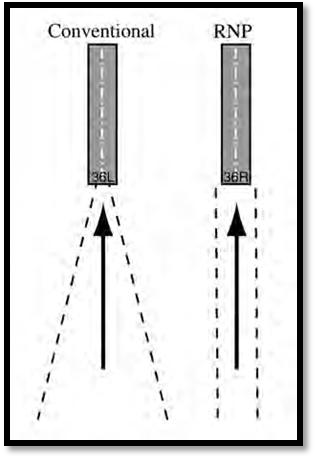
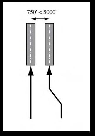
5.10.7.1.2. RNP Parallel Approach (RPA) Operations. RNP SAAAR procedures can be used for parallel approaches where the runway separation is adequate (Figure 5.13). Parallel approach procedures can be used either simultaneously or as standalone operations. They may be part of either independent or dependent operations depending on the ATC ability to provide radar monitoring.
Figure 5.13. RNP Parallel Approach (RPA).
- 5.10.7.1.3. RNP Parallel Approach Runway Transitions (RPAT) Operations. RPAT approaches begin as a parallel IFR approach operation using simultaneous independent or dependent procedures. (Figure 5.14). Visual separation standards are used in the final segment of the approach after the final approach fix, to permit the RPAT aircraft to transition in visual conditions along a predefined lateral and vertical path to align with the runway centerline.
Figure 5.14. RNP Parallel Approach Runway Transitions (RPAT).
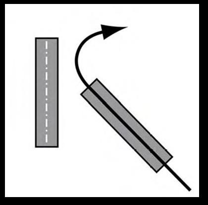
- 5.10.7.2.4. RNP Converging Runway Operations. At airports where runways converge, but may or may not intersect, an RNP SAAAR approach can provide a precise curved missed approach path that conforms to aircraft separation minimums for simultaneous operations (Fig 5.15). By flying this curved missed approach path with high accuracy and containment provided by RNP, dual runway operations may continue to be used to lower ceiling and visibility values than currently available. This type of operation allows greater capacity at airports where it can be applied.
Figure 5.15. RNP Converging Runway Operations.
5.11. Database Issues for RNAV and GPS Navigation.
GPS and other RNAV procedures rely on data extracted from the aircraft navigation database. The potential for serious navigation errors is created by inherent properties of database creation and its use by aircrew and aircraft systems. In order to mitigate these potential errors crews must be familiar with database issues and required procedures.
5.11.1. Aircraft use navigation databases provided by either National Geospatial-Intelligence Agency (NGA) (i.e. DAFIF) or a commercial vendor (i.e. Jeppesen). These databases contain a worldwide list of airports, navigation aids, waypoints, and instrument procedures. Outside the US NAS, this data is provided by host nations, and is not necessarily quality checked by database providers during database creation. Navigation data may be filtered and tailored to meet individual aircraft requirements. Jeppesen tailors their data to meet customer specifications, while DAFIF data is filtered and formatted by outside contractors. Updated navigation data is published on a 28-day cycle.
5.11.1.1. Database Requirements. In order to use GPS for the terminal area, all procedures (DP, Standard Terminal Arrival (STAR), IAP) must be retrieved in their entirety from a current, approved navigation database. Only those approaches included in the receiver database are authorized, and must display as full approaches (not advisory approaches which would not allow pilot to "arm" the approach).
- 5.11.1.1.1. Manual Data Base Manipulation. Users may not alter terminal procedures retrieved from the equipment database. However, this requirement does not prevent the storage of "user-defined" data. This requirement also does not preclude aircrew from complying with ATC instructions by proceeding direct to a point on a STAR/DP or by receiving ATC vectors onto course. This "user-defined" data, however, cannot be part of a terminal procedure, to include IAF or feeder fixes.
5.11.2. Database related errors have occurred at all stages of database development and use. Host nations have provided inaccurate data; database providers have introduced errors during database creation and aircraft specific tailoring; aircrew have selected incorrect waypoint/procedure data; finally, aircraft flight management systems/navigation computers have flown instrument procedures in a manner that does not match the charted procedure.
5.11.3. A paper or EFB copy of the applicable instrument procedure (IAP, SID, STAR) must always be available and crosschecked in the terminal environment.
5.11.3.1. Data Base Procedures.
5.11.3.1.1. Prior to flight, crews must check navigation database validity. If the database has expired, the crew:
5.11.3.1.1.1. May continue a mission with an expired database if the database information required for the flight can be verified with current FLIP.
5.11.3.1.1.2. Shall get the database updated at the first opportunity.
5.11.3.1.1.3. May not use the database to fly procedures that require terminal or better accuracy (i.e. terminal or approach).
5.11.4. Defining Airways.
5.11.4.1. Conventional (Overlay) Airways. Appropriately certified RNAV equipment may be used to fly conventional airways (e.g. FAA J/V routes). These routes may be either retrieved from the aircraft database or constructed by manually entering waypoints.
5.11.4.1.1. If within aircraft capabilities, conventional airways should be retrieved from the aircraft database using the airway identifier.
5.11.4.1.2. If airways cannot be retrieved from the database using the airway identifier, conventional airways may be constructed by manual entry of associated waypoints/NAVAIDS. These waypoints/NAVAIDS should be retrieved from the database by waypoint name if possible. Entry of all airway waypoints is not required. At a minimum, all compulsory waypoints, all NAVAIDS, and any waypoint associated with a change in course must be entered. On crewed aircraft, if airways are entered manually, waypoint sequence must be verified by another crew member.
5.11.4.2. RNAV Airways. RNAV airways should be retrieved in their entirety from the database using the airway identifier. If entered manually, aircrew must ensure that all waypoints are entered and flyby/flyover attributes are correctly entered.
5.11.5. RNAV Terminal Area Operations. As the production of stand-alone GPS approaches has progressed, many of the original overlay approaches have been replaced with stand-alone procedures specifically designed for use by GPS systems. The title of the remaining GPS overlay procedures has been revised on the approach chart to "or GPS" (e.g., VOR or GPS RWY 24). Therefore, all the approaches that can be used by GPS now contain "GPS" in the title (e.g., "VOR or GPS RWY 24," "GPS RWY 24," or "RNAV (GPS) RWY 24"). During these GPS approaches, underlying ground-based NAVAIDs are not required to be operational and associated aircraft avionics need not be installed, operational, turned on or monitored (monitoring of the underlying approach is suggested when equipment is available and functional). Existing overlay approaches may be requested using the GPS title, such as "GPS RWY 24" for the VOR or GPS RWY 24.
5.11.5.1. Some databases may not contain all transitions or departures from all runways. Terminal area and instrument approach procedures must be retrieved in their entirety from the navigation database. These procedures may not be modified or entered manually.
5.11.5.2. Prior to commencing a terminal area or instrument approach procedure, crews must confirm waypoint name, sequence, course, distance, and altitude information match charted information (to include the missed approach segment). Waypoint type (flyby vs. flyover) should also be confirmed if this information is available. MAJCOMS should establish procedures for their crews to perform these required actions.
5.11.5.3. In the event of differences between the terminal procedure chart or approach chart and database, the published approach chart, supplemented by NOTAMs, holds precedence and the database may not be used to fly terminal area or instrument approach procedures except as noted below.
5.11.5.3.1. In some cases, waypoints in the navigation database may differ from the charted instrument procedure. The differences listed below are acceptable and do not preclude use of the database procedure.
5.11.5.3.1.1. Step down fixes depicted on the approach chart may not be contained in the aircraft database. Pilots are responsible for ensuring compliance with applicable step down fixes regardless of whether or not they are in the aircraft database.
5.11.5.3.1.2. The database may contain some waypoints (capture fixes, and a point in lieu of a FAF for non-FAF overlay approaches) that are not depicted on the approach chart.
5.11.5.3.2. Small differences may exist in distances between waypoints. For GPS and RNAV approaches, the maximum allowable difference is 0.1nm. If distance information varies by more than these tolerances, the procedure shall not be flown. If the FMS does not display distances to the tenth of a mile during the approach review, then an acceptable technique would be for the pilot to confirm the distance to the next approach waypoint to a tenth of a mile on the EHSI at each changeover point.
5.11.5.3.3. Computation of the GPS final approach course is based on the station magnetic variation retrieved from the aircraft magnetic variation database. Many aircraft lack the capability to update the magnetic variation database. This will cause a difference between the displayed GPS final approach course and the charted final approach course in the IAP. The discrepancy between displayed and charted magnetic variation will depend on discrepancy between aircraft magnetic variation database (age of database) vs. magnetic variation upon which charted approach course is based (date of magnetic variation survey). Variation between charted final approach course in the IAP and the final approach course computed by the aircraft should be no more than 5 degrees. If the two differ by more than 5 degrees, the procedure is not authorized.
5.11.5.4. Crews must be knowledgeable of system limitations and be ready to manually intervene with RNAV or GPS equipment if necessary. Certain segments of a missed approach, DP, or SID may require some manual intervention by the pilot, especially when radar vectored or required to intercept a specific course to a waypoint.
5.11.5.5. Due to aircraft specific limitations, on some occasions aircraft may not fly a database procedure as indicated on the chart, even though the procedure is correctly coded in the database. This is especially true of missed approach and DP operations that have closely spaced waypoints or require turns initiated at an associated altitude. Crews must carefully monitor aircraft performance to ensure adherence to the charted procedure.
5.11.6. WGS-84 is the worldwide charting standard for coding database information. The use of this common reference system is required to ensure accurate navigation. Although most nations have signed up to the WGS-84 standard, there is no means of ensuring compliance, and not all data from foreign nations is developed IAW WGS-84. A number of database discrepancies have been reported in foreign airspace. Aircrews must monitor underlying ground based navigation aids when available. In the event of discrepancy between RNAV/GPS information and the underlying navigation aids, crews must revert to using underlying ground-based navigation data.
5.11.7. Both Jeppesen and NGA (DAFIF) have established procedures for informing crews of known database problems. Crews must check database NOTAMs prior to flight for information on any planned RNAV or GPS procedures.
- 5.11.7.1. NGA (DAFIF) database NOTAMs associated with a particular airfield are class "W" NOTAMs and may be obtained by entering an airfield identifier in the Joint Chiefs of Staff (JCS) NOTAM web site (https://www.notams.jcs.mil/dinsQueryWeb). DAFIF NOTAMs not associated with a particular airfield (airway NOTAMs, etc.) may be obtained by consulting FLIP change notices via the DAFIF NOTAMs link on the JCS NOTAM web site.. The Jeppesen NOTAM page contains information on airfield specific procedures at the top of the page and has links to regional information at the bottom of the page. Jeppesen database NOTAMs may be accessed through the links section of the JCS NOTAM web site.