Chapter 13: LANDING FROM INSTRUMENT APPROACHES
13.1. Planning the Approach and Landing.
A successful approach and landing in marginal weather conditions requires considerable planning, which should begin before the flight. Checking the forecast weather, winds, NOTAMs, and runway conditions at your destination and alternate will normally help you determine the runway and type of approach that is likely to be used. A study of the instrument approach procedure for the destination airport will show the approach as well as the runway layout, obstructions, type of lighting installed, and minimum data.
13.2. Transitioning From Instrument to Visual Flight Conditions.
The transition from instrument to visual flight conditions varies with each approach. Pilots seldom experience a distinct transition from instrument to visual conditions during an approach in obscured weather. Obscured conditions present you with a number of problems not encountered during an approach that is either hooded or has a cloud base ceiling. At the point where the hood is pulled or the aircraft breaks out below the ceiling, the visual cues used to control the aircraft are usually clear and distinct, and there is instantaneous recognition of the position of the aircraft in relation to the runway. With obscured ceilings or partially obscured conditions, the reverse is usually true; visual cues are indistinct and easily lost, and it is difficult to discern aircraft position laterally and vertically in relation to the runway. Consider every factor that might have a bearing on the final stages of an approach and landing. The visibility, type of weather, expected visual cues, and even crew procedures and coordination are some of the tangibles requiring careful consideration. Preparation and understanding are the keys that will make the transition smooth and precise. Only through a thorough understanding of the weather environment and how it affects the availability and use of visual cues will you be prepared to transition safely and routinely. The following information deals with some of the conditions you may encounter during this phase of flight.
13.2.1. Straight-In. When flying a straight-in approach in VMC, the pilot has almost unlimited peripheral visual cues available for depth perception, vertical positioning, and motion sensing. Even so, varying length and width of unfamiliar runways can lead to erroneous perception of aircraft height above the runway surface. A relatively wide runway may give the illusion that the aircraft is below a normal glide path; conversely, a relatively narrow runway may give the illusion of being high. With an awareness of these illusions under unlimited visibility conditions, it becomes easy to appreciate a pilot's problems in a landing situation in which the approach lights and runway lights are the only visual cues available.
13.2.2. No Vertical Guidance. Instrument approach lights do not provide adequate vertical guidance to the pilot during low visibility instrument approaches. In poor visibility, especially when the runway surface is not visible, or in good visibility at night, there simply are not enough visual cues available to adequately determine vertical position or vertical motion. Studies have shown that the sudden appearance of runway lights when the aircraft is at or near minimums in conditions of limited visibility often gives the pilot the illusion of being high. They have also shown that when the approach lights become visible, pilots tend to abandon the established glide path, ignore their flight instruments and instead rely on the poor visual cues. Another similar situation occurs when a pilot flies into ground fog from above. If the pilot initially sees the runway or approach lights, these cues will tend to disappear as the pilot enters the fog bank. The loss of these visual cues will often induce the illusion or sensation of climbing. These situations of erroneous visual cues convincing the pilot that the aircraft is above normal glide path generally result in a pushover reaction, an increase in the rate of descent, and a short or hard landing.
13.2.3. Descent Rate. Since approach lights are usually sighted close to the ground in limited visibility, an increase in the rate of descent during the final approach when the aircraft is very close to the ground may create a situation in which sufficient lift cannot be generated to break the rate of descent when the pilot realizes he or she will land short.
13.2.4. Crosscheck. A recommended method to ensure against a dangerously high rate of descent and a short or hard landing is to maintain continuous crosscheck of the GSI or flight director and pay continuous attention to PAR controller instructions as well as VVI and ADI indications. The pilot should establish predetermined limitations on maximum rates of descent for the aircraft that he or she will accept when landing out of a low visibility approach. Exceeding these limits during the transition to landing should result in a goaround and missed approach in the interest of aircraft and aircrew safety.
13.2.4.1. Restrictions to Visibility. There are many phenomena, such as rain, smoke, snow, and haze, which may restrict visibility. When surface visibility restrictions do exist and the sky or clouds are totally hidden from the observer, the sky is considered totally obscured and the ceiling is the vertical visibility from the ground. If you are executing an approach in an obscured condition, you will not normally see the approach lights or runway condition as you pass the level of the obscured ceiling. You should be able to see the ground directly below; however, the transition from instrument to visual flight will occur at an altitude considerably lower than the reported vertical visibility. In partially obscured conditions, vertical visibility is not reported since the ground observer can see the sky through the obscuration. When clouds are visible with a partial obscuration, their heights and amounts are reported. The amounts (in 8ths) of the sky or clouds obscured by a partial obscuration are included in the remarks section of weather reports. Although this may help clarify the reported conditions in many cases, it still does not provide an idea of the height at which visual cues will be sighted or the slant range visibility. In some cases the partial obscuration can be associated with shallow patchy fog so you can expect to lose visual references once the fog condition is entered. Also of concern is the visual range at which you will be able to discern visual cues for runway alignment and flare. Be aware that the runway visibility or runway visual range (RVR) may not be representative of the range at which you will sight the runway. In fact, slant range visibility may be considerably less than the reported RVR. Knowledge of these various factors will aid you in making a safe, smooth transition from instrument to visual flight.
13.2.4.1.1. Shallow Fog. Fog that extends no more than 200 feet in height is considered shallow fog and is normally reported as a partial obscuration. Since the fog may be patchy, it is possible that the visual segment may vary considerably during the approach and rollout. RVR may not be representative of actual conditions in this situation if measured by transmissometer located in an area of good visibility. One of the most serious problems with this type of fog stems from the abundance of cues available at the start of the approach. You may see the approach lighting system and possibly even some of the runway during the early stages of the approach. However, as the fog level is entered, most or all the cues become confused and disoriented. In these conditions, you should not rely entirely on visual cues for guidance. They can be brought into the crosscheck to confirm position, but instrument flight must be maintained until visual cues can be kept in view and the runway environment can provide sufficient references for alignment and flare.
13.2.4.1.2. Deep Fog. Fog that extends to a height of several hundred feet usually forms a total obscuration. You will not normally see cues during the early portion of an approach. Most likely, you will pick up cues from only the last 1,000 feet of the approach lighting system. From a US standard approach lighting system, in rapid succession you will probably see cues from the 1,000-foot roll bar, the last 1,000 feet of the centerline approach lights, red terminating bar, red wing lights, green threshold lights, and the high intensity runway edge lights. If operating at night and the strobe lights are on, these may produce a blinding effect. Care should be taken with the use of landing lights as they also may cause a blinding effect at night. The transition from an approach in a total obscuration involves the integration of visual cues within the crosscheck during the latter portion of the approach. Again, be thoroughly familiar with the approach lighting system to develop the proper perspective between these cues and the runway environment.
13.2.4.1.3. Fog Below Clouds. This fog is usually reported as a partial obscuration below a cloud ceiling. After penetrating through a ceiling, visibility usually increases when you descend below the cloud ceiling. Therefore, the transition from instrument to visual flight is sharper, with more pronounced use of visual cues after passing the ceiling. However, with fog below clouds all of the problems mentioned above with shallow fog and deep fog may be found. Night approaches may produce the sensation that the aircraft is high once the cloud base is passed. You should continue on instruments, cross-checking visual cues to confirm runway alignment. During the flare you may experience a sensation of descending below the surface of the runway. This will be especially pronounced at facilities with 300-foot wide runways. In either case, avoid abrupt or large attitude changes.
13.2.4.1.4. Advection Fog. Advection fog can present wind and turbulence problems not normally associated with other types of fog. Advection fog may possess characteristics similar to shallow, deep, or cloud base fog. It may be more difficult to maintain precise instrument flight because of turbulence. The characteristics of advection fog will be related to the wind speed increases. Wind greater than 15 knots usually lifts the fog and it forms a cloud base. The best procedure is to be aware of the conditions that might be encountered and to integrate visual cues within the crosscheck during the later portion of the approach. Also closely monitor airspeed because of the effects of turbulence and crosswinds.
13.2.4.1.5. Ice Fog. This type of fog is most common to the Arctic region; however, it can occur in other areas if the air temperature is below approximately 0° C (32° F). It consists of a suspension of ice crystals in the air and is more common around airports and cities. Condensation nuclei caused by human activity often cause the fog to form. When there is little or no wind, it is possible for an aircraft to generate enough fog during landing or takeoff to cover the runway and a portion of the field. Depending on the atmospheric conditions, ice fogs may last for several minutes or days. The piloting hazards and procedures are basically the same as with other fogs.
13.2.4.1.6. Rain. Approaches and the ensuing transition to visual flight can be very hazardous since moderate to heavy rain conditions can seriously affect the use of visual cues. Night approaches in these conditions can be even more critical as flashing strobes or runway end identifier lights may distract you. Transition to visual flight can be severely hampered by the inability to adequately maintain aircraft control and interpret the instruments as a result of gusty or turbulent conditions. The moderate or heavy rain conditions can also render the rain removal equipment ineffective, causing obscuration of visual cues at a critical time during the transition. In these conditions, be prepared for an alternate course of action and act without hesitation to prevent the development of an unsafe situation.
13.2.4.1.7. Snow. Blowing snow is accompanied by many of the same hazards as rain, such as turbulence, difficulties in reading the flight instruments, obscured visual cues, and aircraft control problems. Of special interest will be a lack of visual cues for runway identification for the visual portion of the approach. The approach and runway lights will provide some identification; however, runway markings and the contrast with relation to its surroundings may be lost in the whiteness. Therefore, depth perception may be difficult, requiring more emphasis on instruments for attitude control. It is extremely important to avoid large attitude changes during approaches in snow.
13.2.4.2. Visual Cues.
13.2.4.2.1. Runway Contact Point. Approach lights, runway markings, lights, and contrasts are the primary sources of visual cues. At some facilities, touchdown zone and centerline lights may also be available. Become familiar with the lighting and marking patterns at your destination and correlate them with the weather so you will be prepared to transition to visual flight. In minimum visibility conditions, the visual cues and references for flare and runway alignment are extremely limited compared to the normal references used during a visual approach. Therefore, the aircraft's projected runway contact point may not be within your visual segment until considerably below published minimums.
- 13.2.4.2.1.1. WARNING: Any abrupt attitude changes to attempt to bring the projected touchdown point into your visual segment may produce high sink rates and thrust or lift problems at a critical time. Those so-called duck-under maneuvers must be avoided during the low visibility approach.
13.2.4.2.2. Duck-under. Another potential duck-under situation occurs when you attempt to land within the first 500 to 1,000 feet of the runway after breaking out of an overcast condition. In this case, you may attempt to establish a visual profile similar to the one you use most often. Establishing the visual profile usually involves reducing power and changing attitude to aim the aircraft at some spot short of the end of the runway. In this maneuver you may attempt to use as much of the available runway as possible because of a short runway or due to poor braking conditions. The duck-under is not recommended since high sink rates and poor thrust/lift relationships can develop which may cause undershoots or hard landings. Base your landing decision upon the normal touchdown point from the instrument approach, and if stopping distances are insufficient, proceed to an alternate.
Figure 13.1. Downward Vision Angle.
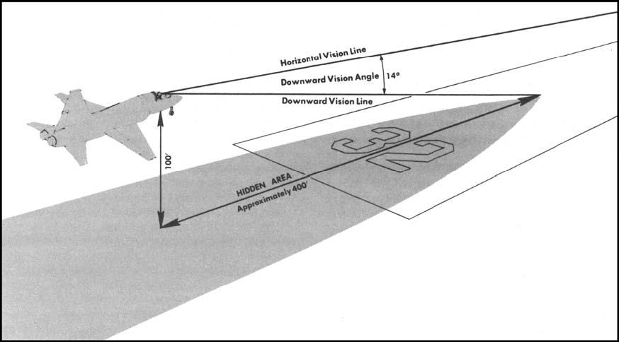
13.2.4.3. Downward Vision Angle (Figure 13.1). There is an area hidden by the nose of an aircraft that cannot be seen from the cockpit. The downward vision line from the pilot's eye projected over the nose of the aircraft forms an angle with the horizontal vision line. This angle is called the "downward vision angle." An aircraft with a 14° downward vision angle 100 feet above the surface will conceal about 400 feet beneath its nose. Consider an approach in 1,600-foot visibility. This means your visual segment at 100foot elevation with a 14° downward vision will be reduced to about 1,200 feet. Other factors, such as a nose-high pitch attitude and a slant range visibility less than the RVR, can further reduce your visual segment.
13.2.4.4. Pilot Reaction Time. At 100-foot elevation and a 3° glide slope, an aircraft is approximately 1,900 feet from the runway point of intercept (RPI). If your aircraft's final approach speed is 130 knots (215 feet per second), you have about 9 seconds to bring visual cues into the crosscheck, ascertain lateral and vertical position, determine a visual flight path, and establish appropriate corrections. More than likely, 3 to 4 seconds will be spent integrating visual cues before making a necessary control input. By this time, the aircraft will be 600 to 800 feet closer to the RPI, 40 to 60 feet lower, and possibly well into the flare. Therefore, it is absolutely essential to be prepared to use visual cues properly and with discretion during the final stages of a low visibility approach. Prior to total reliance on visual information, confirm that the instrument indications support the visual perspective.
13.2.4.5. Crew Procedures.
13.2.4.5.1. Pilot Monitoring (PM). A PM can assist the pilot flying (PF) in a number of ways. The PM can fly the approach, control airspeed, be responsible for communications, direct the checklist, perform the missed approach, establish aircraft configurations, or perform any other duties assigned by the PF. However, the PM must understand exactly what those duties and responsibilities are before the approach.
13.2.4.5.2. Technique One. One technique that has proven quite successful has been to allow highly qualified copilots to fly the approach, while the pilot makes the decision to continue or go-around at DH. The PM assumes control if a landing is to be made; if not, the copilot executes the go-around. This procedure puts fewer burdens on the pilot, allowing more time to obtain information from the visual cues for landing. If the approach is unsatisfactory or insufficient visual references are available to continue the approach at DA/DH, the copilot, since the aircraft is on instruments, is prepared to execute a missed approach on command. If the pilot executes the approach, the copilot may be allowed to control power or airspeed until DA/DH where the pilot assumes control for the landing or missed approach.
13.2.4.5.3. Technique Two. Another technique is to have the PM the approach continue to monitor flight instruments from DA/DH or minimum descent altitude to touchdown and notify the PF the approach of excessive deviations in rates of descent, glide slope, course, or airspeed. This technique will help detect duck-under maneuvers and will prevent both pilots from being deceived by a visual illusion that may be present.
13.2.4.5.4. Technique Three. A final technique is to have the autopilot fly the approach to the MDA/DA/DH and then have the PF assume control to either land or execute the go-around as required. This technique can be quite helpful especially after a long duty day and/or with instrument conditions.
13.3. Approach Lighting Systems.
13.3.1. Types of Approach Lighting Systems.
13.3.1.1. Visual Aids. Approach lighting systems are visual aids used during instrument conditions to supplement the guidance information of electronic aids such as VOR, TACAN, PAR, and ILS. The approach lights are designated high intensity (the basic type of installation) and medium intensity, according to candlepower output.
13.3.1.2. Adjustment. Most runway and approach light systems allow the tower controller to adjust the lamp brightness for different visibility conditions, or at a pilot's request. The extreme brilliance of high intensity lights penetrates fog, smoke, precipitation, etc., but may cause excessive glare under some conditions.
13.3.1.3. Depiction. The approach lighting systems now in use, along with their standard lengths, appear in the FIH.
13.3.1.4. Pilot Activation. Some airports have installed airport lighting systems that can be activated by the pilot "keying the microphone" on selected frequencies. Information concerning these systems can be found in the FIH and Terminal FLIP.
13.3.2. Runway End Identifier Lights (REIL). Runway end identifier lights are installed at many airfields to help identify the approach end of the runway. The system consists of two synchronized flashing lights, one of which is located laterally on each side of the runway threshold facing the approach area. They are effective for identifying a runway that lacks contrast with the surrounding terrain or which is surrounded by other lighting, and for approaches during reduced visibility.
13.3.3. Visual Glide Slope Indicators (VGSI).
13.3.3.1. There are many different types of visual glide slope indicators in use, many in conjunction with instrument approach procedures. They provide visual glide path guidance from the instrument approach minimums to a point on the runway and can provide assistance in the transition from instrument to visual flight. Configurations are depicted in the FIH.
- 13.3.3.1.1. Depending upon which approach is flown, the visual glide path indicator may not guide the aircraft to the same point on the runway as the instrument approach being flown. This is depicted on many approach procedures with a note such as, "PAPI and ILS RPI not coincident." This is common at airports with frequent jumbojet operations (C-5, 747, 777, etc). The VGSI at these airports is frequently adjusted to compensate for the greater vertical distance between the ground and the cockpit in these large aircraft. A smaller aircraft (KC-135, C-130, fighter, etc) that follows these VGSI indications to touchdown will touchdown beyond their normal touchdown point.
13.4. Runway Lighting Systems (Figure 13.2).
Two basic runway lighting systems are used to aid the pilot in defining the usable landing area of the runway. These systems are Runway Edge Lights and Runway Centerline and Touchdown Zone Lights. For discussion of airport markings and signs used during ground operations, see AFI 11-218, Aircraft Operations and Movement on the Ground.
13.4.1. Runway Edge Lighting. The runway edge lighting system is a configuration of lights that defines the limits of the usable landing area. The lateral limits are defined by a row of white lights on either side of the runway. The longitudinal limits are defined at each end by the threshold lighting configuration. This configuration includes threshold lights, a prethreshold light bar, and a terminating bar. The threshold lights emit green light toward the approach end of the runway and red light toward the rollout end of the runway.
Figure 13.2. Runway Lighting Systems.
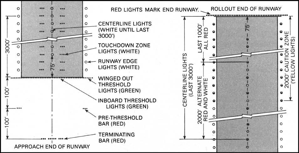
13.4.1.1. HIRL. The High Intensity Runway Lighting (HIRL) system is the basic type of installation used by the Air Force. These elevated bi-directional lights, which extend the length of the runway, emit a white light the entire length of the runway at some military fields. Most military and all civil field HIRLs also emit a white light except in the caution zone, which is the last 2,000 feet (610m) of an instrument runway or one-half the runway length, whichever is less. The lights in the caution zone emit a yellow light in the direction of the approach end and white light in the opposite direction. The yellow lights are intended for rollout information after landing and are sometimes used in place of runway remaining markers.
13.4.1.2. MIRL. The Medium Intensity Runway Lighting (MIRL) system, which consists of elevated, omni-directional lights, may be installed on runways that are not to be used under IMC due to impaired clearance, short length, or other factors.
13.4.2. Runway Centerline and Touchdown Zone Lighting. The runway centerline and touchdown zone lighting systems are designed to facilitate landings, rollouts, and takeoffs under adverse day and night low visibility conditions. The touchdown zone lights, which define the touchdown area, are primarily a landing aid while the centerline lights are most effective for rollout and takeoff.
13.4.2.1. Touchdown Zone Lighting. The touchdown zone lighting system consists of two rows of high intensity light bars arranged on either side of the runway centerline. Each bar consists of three unidirectional white lights toward the approach area. The two rows of light bars are 3,000 feet long and extend from the threshold of the runway toward the rollout end of the runway.
13.4.2.2. Runway Centerline Lighting. The runway centerline lighting system is a straight line of lights located along the runway centerline. The system starts 75 feet (23m) from the threshold and extends down the runway to within 75 feet of the rollout end of the runway. The last 3,000 feet are color coded for landing rollout information. The last 3,000-foot to 1,000-foot section displays alternate red and white lights, while the last 1,000-foot section displays all red lights.
13.5. Runway Markings.
Runway markings are designed to make the landing area more conspicuous and to add a third dimension for night and low visibility operations. For discussion of airport and runway markings, see AFI 11-218.
13.6. Circling Approaches.
13.6.1. General Procedures. Circling to land is a visual flight maneuver. When the instrument approach is completed, it is used to align the aircraft with the landing runway. The circling MDA and weather minima to be used are those for the runway to which the instrument approach is flown (this is not always the landing runway). The circling minima listed on IAPs apply to all approach types on the IAP (RNAV (GPS), ILS, LOC, VOR, TACAN, etc.). However, since the MAP associated with the precision approach is determined by the pilot in terms of a DH and not a specific point along the final approach course, it becomes difficult to ascertain when to discontinue the approach if visual conditions are not encountered. Therefore, pilots are cautioned to ensure the aircraft is within the appropriate circling radius before abandoning the precision glideslope, if planning to circle from a precision final approach.
- 13.6.1.1. Circling from RNAV/GPS Approaches. Circling may be accomplished from an RNAV (GPS) approach if circling minimums are published. However, depending on the type of circling maneuver required, following RNAV (GPS) vertical guidance to the circling MDA may result in visually acquiring the airport environment too late to accomplish a safe circling maneuver. Pilots must ensure they remain within the required obstacle clearance radius and maintain situational awareness, especially in reduced visibility. In reduced visibility, pilots must maintain situational awareness and insure they remain within the required obstacle clearance radius. If there is any doubt as to maintaining required distance, or a loss of situational awareness, accomplish the missed approach and request an alternate approach.
13.6.2. Instructions. If the controller has a requirement to specify the direction of the circling maneuver in relation to the airport or runway, the controller will issue instructions in the following manner: "Circle (direction given as one of eight cardinal compass points) of the airport/runway for a right/left base/downwind to runway (number)." For example, "Circle west of the airport for a right base to runway one eight."
- 13.6.2.1. NOTE: Obstruction clearance areas are determined by aircraft category. Maneuver the aircraft to remain within the circling area for your aircraft category (see AFMAN 11-217V3 for radii of circling approaches). If it is necessary to maneuver at speeds in excess of the upper limit of the speed range authorized for your aircraft's category, use the landing minima for the category appropriate to the maneuvering speed. When you request circling MDA from the controller for a circling ASR approach, state your aircraft category.
Figure 13.3. The Circling Approach.
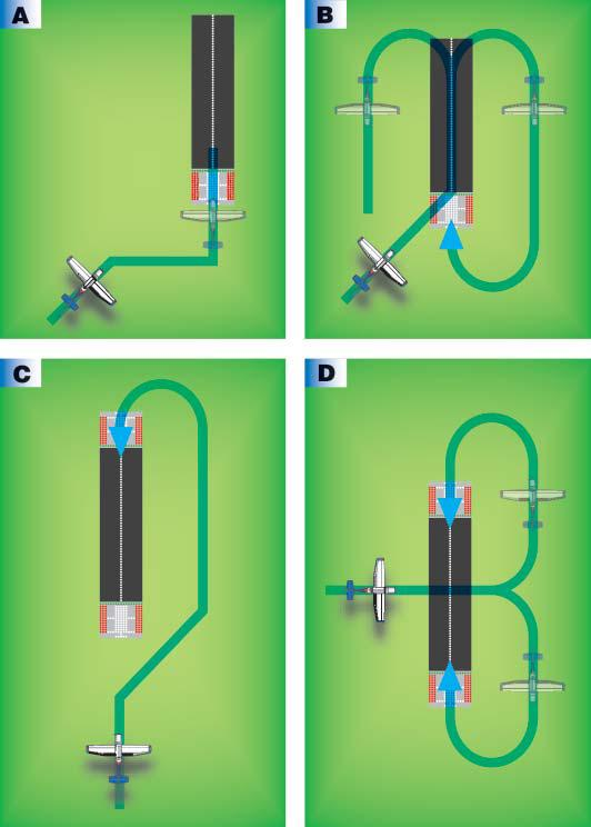
13.6.3. Accomplishing the Approach (Figure 13.3).
13.6.3.1. Descent. After descending to circling minimum descent altitude and when the airport environment is in sight, determine if the ceiling and visibility are sufficient for performing the circling maneuver. The airport environment is considered the runways, its lights and markings, taxiways, hangars, and other buildings associated with the airport. (Since the MDA is a minimum altitude, a higher altitude may be maintained throughout the maneuver.)
13.6.3.2. Pattern. Choose a pattern that best suits the situation. Maneuver the aircraft to a position that allows you to keep as much of the airport environment in sight as possible. Consider making your turn to final into the wind if this maneuvering allows you to also keep the airport environment in sight. You may make either left or right turns to final unless you are directed by the controlling agency to turn in a specific direction or are limited by restrictions on the approach chart or IFR Supplement.
13.6.3.3. Weather -- High Ceiling/Good Visibility. If weather permits, fly the circling approach at an altitude higher than the circling MDA, up to your normal VFR traffic pattern altitude. This allows the maneuver to be flown with a more familiar perspective and better visual cues. Do not descend below circling MDA until in a position to place the aircraft on a normal glide path to the landing runway. (In order to prepare pilots for the worst situation fly practice circling approaches at the circling MDA if feasible and conditions permit.)
13.6.3.4. Weather -- Low Ceiling/Restricted visibility. If weather does not permit circling above the MDA, do not descend below circling MDA until the aircraft is in a position to execute a normal landing. Descend from the MDA as necessary to place the aircraft on a normal glide path to the landing runway.
13.6.3.5. Missed Approach. If there is any doubt whether the aircraft can be safely maneuvered to touchdown, execute the missed approach.
- 13.6.3.5.1. CAUTION: Be aware of the common tendency to maneuver too close to the runway at altitudes lower than your normal VFR pattern altitude. Using the same visual cues that you use from normal VFR pattern altitudes causes this. Select a pattern that displaces you far enough from the runway that will allow you to turn to final without overbanking or overshooting final.
13.7. Side-Step Maneuver Procedures.
Where a side-step procedure is published, aircraft may make an instrument approach to a runway or airport and then visually maneuver to land on an alternate runway specified in the procedure. Landing minimums to the adjacent runway will be higher than the minimums to the primary runway, but will normally be lower than the published circling minimums.
13.7.1. Phraseology. Examples of ATC phraseology used to clear aircraft for these procedures are: "Cleared for ILS runway seven left approach. Side-step to runway seven right."
13.7.2. Begin Side-step. Pilots are normally expected to commence the side-step maneuver as soon as possible after the runway or runway environment is in sight. Typically this occurs inside the FAF. Beginning the side-step maneuver prior to the FAF could cause a conflict with other traffic, especially when using parallel runways. Compliance with minimum altitudes associated with stepdown fixes is expected even after the side-step maneuver is initiated.
13.7.3. Lose Visual. As in a circling approach, if you lose visual reference during the maneuver, follow the missed approach specified for the approach procedure just flown, unless otherwise directed. An initial climbing turn toward the landing runway will ensure that the aircraft remains within the obstruction clearance area.