Chapter 3: NAVIGATION INSTRUMENTS
3.1. Application.
The navigation instruments explained in this chapter are still common in many USAF aircraft or are incorporated in digital (glass) cockpit displays. These instruments are the radio magnetic indicator (RMI), course indicator (CI), range indicator, bearing-distance heading indicator (BDHI), flight director, and Flight Management System (FMS).
3.2. Basic Systems.
3.2.1. Radio Magnetic Indicator (RMI) (Figure 3.1). The RMI displays aircraft heading with navigational bearing data. It normally consists of a rotating compass card and two bearing pointers. The compass card is actuated by the aircraft compass system. The aircraft magnetic heading is displayed on the compass card beneath the top index. The bearing pointers display automatic direction finding (ADF), VHF Omni directional Range (VOR), or Tactical Air Navigation (TACAN) magnetic bearing to the selected navigation station. Placards on the instrument or near a selector switch are normally used to identify the bearing pointer display. VOR or TACAN radials are displayed under the tail of their respective bearing pointers. Bearing pointers do not function in relation to instrument landing system (ILS) signals.
Figure 3.1. Navigation Instruments.

- 3.2.1.1. Compass System Malfunction. If there is a malfunction in the compass system or compass card, the ADF bearing pointer continues to point to the station, and displays relative bearing only but the VOR or TACAN pointers may still indicate magnetic bearing. Until verified by radar or other navigational equipment, consider this bearing information unreliable. VOR and TACAN bearing pointers do not "point" to an area of maximum signal strength, as does an ADF. VOR and TACAN navigation receivers electronically measure the magnetic course which is then displayed by the pointers on the RMI.
3.2.2. Course Indicator (CI) (Figure 3.1). The course indicator operates independently of the RMI. It displays aircraft heading and position relative to a selected VOR/TACAN course, and lateral and vertical position relative to an ILS localizer and glide slope. Most USAF aircraft now have the functions of the CI incorporated in the Horizontal Situation Indicator (HSI).
3.2.2.1. VOR or TACAN Display.
3.2.2.1.1. Course indicator. When the course indicator is used to display VOR or TACAN information, aircraft heading and position are indicated relative to a selected course. The desired course is set in the course selector window with the course set knob.
3.2.2.1.2. The Heading Pointer. The heading pointer interfaces with the course set knob and the compass system and displays aircraft heading relative to the selected course. When the aircraft heading is the same as the course selected, the heading pointer indicates 0° heading deviation at the top of the course indicator. The heading deviation scales, at the top and bottom of the course indicator are scaled in 5° increments up to 45°. The TO-FROM indicator indicates whether the course selected, if properly intercepted and flown, will take the aircraft to or from the station. When the aircraft passes a line from the station perpendicular to the selected course, the TO-FROM indicator changes. Aircraft heading has no effect on the TO-FROM indications.
3.2.2.1.3. Course Deviation Indicator. The course deviation indicator (CDI) displays aircraft course deviation relative to the course selected. Most course indicators are adjusted so the CDI is fully displaced when the aircraft is off course more than 10°. Each dot on the course deviation scale represents 5°.
3.2.2.1.4. Course Warning Flag. Appearance of the course warning flag indicates that the course indicator is not receiving a signal strong enough for reliable navigation information. See Chapter 7 for discussion on Navigation Aid (NAVAID) identification.
- 3.2.2.1.4.1. NOTE: Although the course indicator may be receiving a signal strong enough to keep the course warning flag out of view, consider the signal reliable only if the warning flag is not displayed, the station identification is being received and the bearing pointer is pointing to the station.
3.2.2.2. ILS Display.
3.2.2.2.1. Localizer Course. When used to display ILS signals, the course indicator provides precise ILS localizer course information for a specified approach. The following information pertains to course indicator functions and displays when used with an ILS:
3.2.2.2.1.1. The TO-FROM indicator is unusable.
3.2.2.2.1.2. Full-scale deflection. Full-scale deflection on the course deviation scale differs with the width of the localizer course (up to 6°). Example: If the localizer course is 5° wide, then full-scale deflection is 2½° and each dot is 1¼°; if the localizer course is 3° wide, then full-scale deflection is 1½° and each dot is ¾°.
3.2.2.2.1.3. When flying the localizer, the course set knob and course selected have no effect on the CDI display. The CDI displays only if the aircraft is on course or in a 90- or 150-Hz zone of signals originating from the ILS localizer transmitter. The CDI always deflects to the left of the instrument case in the 150Hz zone and to the right in the 90-Hz zone. It centers when the signal strength of both zones is equal. Although the course selected has no effect on the CDI, to enhance situational awareness, the pilot should always set the published inbound FRONT COURSE of the ILS in the course selector window.
3.2.2.2.2. The glide slope indicator (GSI) displays glide slope position relative to the aircraft. Full-scale deflection of the GSI is dependent upon the width of the glide slope. Example: If the glide slope width is 1.4°, full-scale deflection would be .7°, and each dot would be .35°.
3.2.2.2.3. Warning Flags. Appearance of the course or glide slope warning flags indicates that the course or glide slope signal strength is not sufficient. Absence of the identifier indicates the signal is unreliable. See Chapter 7 for discussion on NAVAID identification.
- 3.2.2.2.3.1. CAUTION: It is possible under certain conditions for the CDI or GSI to stick in any position with no warning flags while reliable station identification is being received. Pilots should use extreme caution and maintain good situational awareness while flying an ILS or localizer approach in actual weather conditions.
3.2.2.2.4. Marker Beacon. The marker beacon light and aural tone indicate proximity to a 75-MHz marker beacon transmitter; for example, ILS outer marker (OM), middle marker (MM), inner marker (IM), etc. As the aircraft flies through the marker beacon signal pattern, the light flashes and the aural tone sounds in Morse code indicating the type of beacon. The marker beacon light functions independently of ILS/VOR/TACAN signals.
3.2.3. Range Indicator (Figure 3.1). Range indicators display slant range distance in nautical miles to a DME transponder. For practical purposes, you may consider this a horizontal distance except when the aircraft is very close to the station. DME range information is subject to line-of-sight restrictions and altitude directly affects the reception range. Most USAF aircraft now incorporate DME into the HSI or a separate digital readout display.
Figure 3.2. Bearing Distance Heading Indicator (BDHI).

3.2.4. Bearing-Distance-Heading Indicator (BDHI) (Figure 3.2).
3.2.4.1. BDHI Display. The BDHI displays aircraft heading with navigational bearing data and range information. Except for the range indicator, the BDHI is similar in appearance and function to the RMI previously described.
3.2.4.2. BDHI Components. The BDHI consists of a rotating compass card, two bearing pointers, a range indicator, and a range warning flag. Some BDHIs also have a heading marker, a heading set knob, and a power warning flag.
3.2.4.3. Compass Card Actuation. The compass card is actuated by the aircraft compass system which normally includes pilot-operated controls that permit the BDHI compass card to operate in a slaved or non-slaved direct gyro (DG) mode. In the slaved mode, the aircraft magnetic heading is displayed beneath the top index or lubber line. In the nonslaved DG mode, the compass card serves as a heading reference after being corrected to a known heading. The card is manually corrected for the DG mode by a switch on the compass control panel.
3.2.4.4. Heading Marker. The heading marker, if incorporated, may be positioned on the compass card by use of the heading set knob. Once positioned, the marker remains on a fixed heading. To maintain the selected heading, turn to place the heading marker beneath the upper lubber line.
3.2.4.5. Bearing Pointers. The bearing pointers indicate the magnetic bearing to the selected ADF, VOR, or TACAN station. Placards on the instrument or near a selector switch are used in most aircraft to identify the bearing pointer display.
- 3.2.4.5.1. NOTE: When tuned to an ILS frequency, bearing pointers will normally slave to a position 45 or 90 degrees from the upper lubber line. Refer to flight manual for details.
3.2.4.6. Malfunctions. If there is a malfunction in the compass system or compass card, an ADF bearing pointer continues to point to the station and displays relative bearing only. TACAN/VOR pointers may continue to indicate proper magnetic bearings. Until verified by radar or other navigation equipment, consider this bearing information unreliable.
3.3. Flight Director.
The flight director provides the pilot with displays of pitch and bank attitudes and the navigation situation of the aircraft. The flight director, when combined with round dial performance instruments, is termed the flight director system (FDS). When the flight director is combined with vertical scale instruments it is termed the integrated flight instrument system (IFIS). The three components of the flight director of major interest are the attitude director indicator (ADI), the horizontal situation indicator (HSI), and the flight director computer.
Figure 3.3. Typical Flight Director.
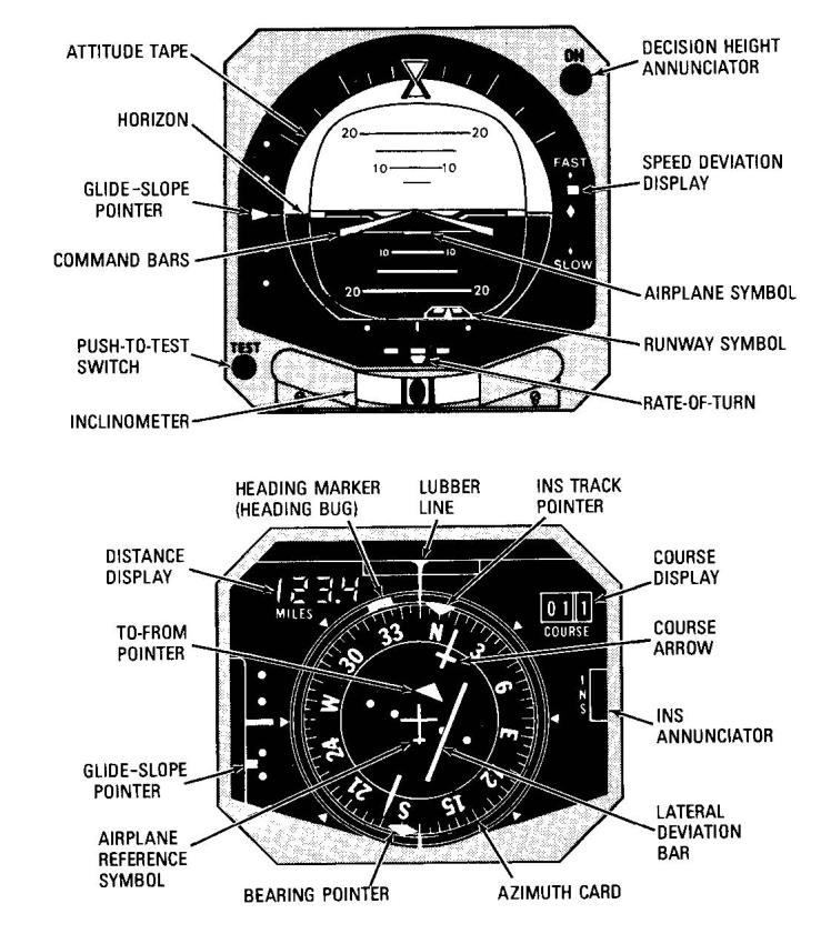
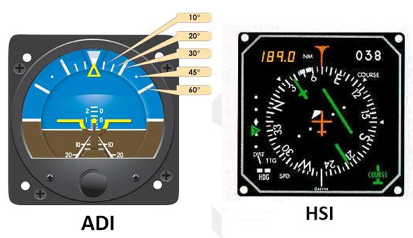
3.3.1. Attitude Director Indicator (ADI) (Figures 3.3 and 3.4).
3.3.1.1. Parts of Attitude Director Indicator. The ADI usually consists of an attitude indicator, rate of turn and slip indications, glide slope indicator, command bars, attitude warning flag, glide slope warning flag, and course warning flag. Additional information displayed on some ADIs includes radar altitude information, approach speed deviation, and a runway symbol that displays lateral and vertical displacement from the runway.
- 3.3.1.1.1. Glide Slope Pointer. The glide slope pointer (GSP) displays glide slope position in relation to the aircraft. If the GSP is above or below center the glide slope is above or below the aircraft respectively. GSP scale deflection differs with the width of the glide slope (1° to 1.8°). Example: If the glide slope width was 1°, fullscale deflection would be ½° and each dot would be ¼° (Figure 3.3).
Figure 3.4. ADI and HSI.
3.3.1.1.2. Command Bars. The command bars display steering information to intercept or maintain a desired flight path. To utilize the steering function, simply "fly" the ADI's aircraft symbol by adjusting the aircraft attitude until it is snugly aligned beneath the command bars. The bars will command the proper pitch and bank to turn, intercept, and maintain a course and altitude.
- 3.3.1.1.2.1. NOTE: Warning flags are incorporated in the ADI to indicate failure or unreliability of presentations. Check the aircraft flight manual for specific warning flags applicable to your aircraft. In some ADIs, if power fails to the pitch and bank steering bars, no warning flags will appear, and the pitch and bank steering bars will center. Monitor the identifier to ensure that the signal is reliable. In most aircraft a warning flag appears when the signal strength is insufficient.
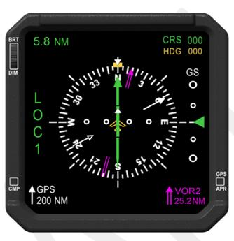
3.3.2. Horizontal Situation Indicator (HSI) (Figures 3.3 and 3.4). The horizontal situation indicator combines the heading indicator, RMI, CI, and range indicator into one display. (See explanations of these functions in previous sections of this chapter.) Additional features available on electronic HSIs include arc formats to display a segment of the standard display as well as map formats used to pictorially display aircraft position in relation to NAVAIDS or waypoints. (Figure 3.5.)
Figure 3.5. Electronic HIS.
3.3.2.1. Course Selector Knob. The course selector knob on most HSI's may be used to select any course by rotating the head of the course arrow to the desired course on the compass card. Check the course selector window for the proper setting.
3.3.2.2. Heading Set Knob. The heading set knob moves the heading marker to a desired heading. With the proper mode selected on the flight director control panel, the heading marker can be slaved to the flight director computer. Thus, when a heading is set, the command bars will command the bank attitude required to turn to and maintain the selected heading.
3.3.3. Flight Director Computer. The flight director computer receives navigation information from the navigation systems and attitude information from the attitude gyro. Depending on the modes available and selected, the computer supplies pitch or bank commands to the command bars of the ADI. The command bars can be used for many functions such as intercepting VOR, TACAN, and Doppler courses or performing data link intercepts. Pitch command information can vary from terrain avoidance to flying a glidepath or changing altitudes. In all cases, the command bars display command information and do not reflect actual aircraft position. Refer to the appropriate flight manual for the specific capabilities of the system installed in your aircraft.
3.3.4. Flight Director Modes.
3.3.4.1. Heading Mode. The flight director will sync the command bars to the heading marker to keep the aircraft on the selected heading.
3.3.4.2. ILS Intercept Mode. The flight director will cause the command bars to steer the aircraft onto and maintain the ILS course selected in the navigation radios.
3.3.4.2.1. Wind drift. Some computers supply wind drift compensation.
3.3.4.2.2. Bank angle. Maximum bank angle commanded is usually 25° to 35°, depending on the system.
3.3.4.2.3. Intercept angle. Maximum intercept angle commanded is normally about 45°.
3.3.4.2.4. ILS Final Approach Mode. Adds pitch inputs to the command bars to fly to and maintain the glideslope. In this mode, commanded bank angle is normally limited to a maximum of 15° and maximum pitch attitude commanded is 10° to 17°, depending on the system.
3.4. Flight Management System (FMS).
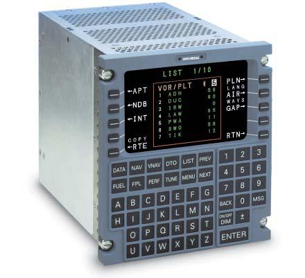
Many newer aircraft are equipped with an FMS consisting of a Flight Management Computer (FMC), one or more Control Display Units (CDU), an internal navigation database, and various displays and annunciators (Figure 3.6). The FMS utilizes aircraft sensors and navigation database information to compute and display aircraft position, performance data, and navigation information during all phases of flight. The FMS may interface and provide guidance commands to autopilot, flight director, and auto-throttle systems.
Figure 3.6. Typical Flight Management System.
3.4.1. Flight Management Computer. The FMC gathers aircraft position information from multiple onboard sensors and navigation aids including VOR, DME, TACAN, Inertial Reference Systems (IRS), Inertial Navigation Systems (INS), Global Positioning System (GPS), and Air Data Computers. Using this aircraft position information, navigation functions such as course and distance to a waypoint, desired track, groundspeed, and estimated time of arrival are computed and displayed on the CDU and other aircraft instruments. Additionally, fuel flow information may be used by the FMC to calculate and update fuel consumption, specific range, and fuel overhead destination information.
3.4.2. Control Display Unit. The CDU allows the aircrew to interface with the FMC. The CDU normally consists of a display screen, data entry pad, and function and line select keys. The CDU allows menu-driven selection of various FMS modes, such as initialization, fuel planning, performance, and navigation. The pilot may input flight plan route and various other flight parameters into the CDU to enhance situational awareness and the navigational capabilities of the aircraft.
3.4.3. Navigation Database. An FMS normally contains an internal navigation database with either regional or worldwide coverage. The database typically includes information on navigation aids, airports, runways, waypoints, routes, airways, intersections, departures and arrivals, and instrument approaches. Aircrews may also store defined routes and waypoints in the database. Navigation databases require periodic updates, normally on a 28-day cycle, to ensure data is current.
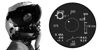
3.5. Single Medium Displays.
A single medium display is a Head-Up Display (HUD), HeadDown Display (HDD), or Helmet-Mounted Display (HMD) (Figure 3.7). These systems can display control, performance, and navigation data in the pilot's outside field of view, enabling him to clear and monitor instruments simultaneously. Information received from HUD equipment that is not certified for sole-reference instrument flight by HQ USAF/A3O must be verified with other cockpit indications.
Figure 3.7. Helmet Mounted Display.
3.5.1. Some single medium displays have the ability to project a Flight Path Marker (FPM) to display vector flight paths. This projection gives a predictive line that shows where the aircraft is going based on current flight parameters. On HUDs the FPM can be used to plan terrain clearance maneuvers on low levels, determine where the aircraft will touch down when landing, etc. Drawbacks to the FPM include the tendency of the display to float around, especially in crosswinds, the bobbing motion of the FPM as it lags behind the movement of the nose of the aircraft, and the degraded usefulness of the FPM when it exceeds the limits of the instrument's field-of-view at high angles of attack and in large drift or yaw situations.
3.5.2. More advanced displays use a Climb/Dive Marker (CDM) as the command flight symbol for vector flying. The CDM will utilize the concept of the above FPM and flight path scale, but both will be caged to the center of the display to prevent the symbology from drifting off the usable area of the instrument.